Method of dosing liquid volumes and apparatus for the execution of the method

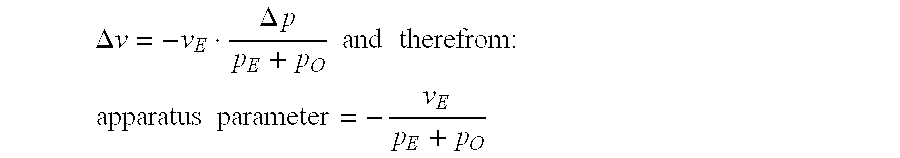
a liquid volume and liquid volume technology, applied in the field of method of dosing liquid volume and apparatus for the execution of the method, can solve the problems of is neglected, and is difficult to determine the volume that flows in within this period, so as to achieve accurate determination of the pickup volume, the effect of reducing the influence of pressure variations on the determination of the taken volume, and reducing the error due to the pressure change in these phases

Active Publication Date: 2007-04-03
EPPENDORF SE
View PDF10 Cites 8 Cited by
  • Summary
  • Abstract
  • Description
  • Claims
  • Application Information

AI Technical Summary

Benefits of technology

[0021]By the negative working pressure block profile that is applied when taking up liquid, the influence of pressure variations on the determination of the taken volume is largely suppressed. Furthermore, by applying a relatively low working pressure, a taking-up duration can be achieved which is long with respect to the phases of build-up and decay of the negative pressure. Through this, the error due to the pressure change in these phases is kept negligibly small. In addition, on account of the negative working pressure block profile, the liquid volume that has been taken up is accurately known at each moment, so that it has not to be awaited until a static pressure balance is reached. Only through this, the detection of the taken volume with the aid of the readjusted driving path is made possible. The taken volume is detected repeatedly or continuously, for instance. At the same time, one or more flow parameter(s) are determined from the negative pressure and the taking duration.
[0022]For releasing the liquid, the knowledge of the flow parameter(s) is used, which describes or describe, respectively, the volume of the liquid flown through the liquid passage per unit of time and pressure. When releasing the liquid, the volume that has been released is calculated with the aid of the flow parameters(s) and the known overpressure on the one hand, and the duration of its action on the other hand. Preferably, the overpressure is constant when releasing the liquid, so that the releasing duration for releasing a volume that has to be released can be easily calculated and the releasing can be stopped when the releasing duration is reached. When the flowing conditions are non-linear, at usual working pressures in a pipette point for instance, according to one form of realisation, the released volume is determined according to a reference pressure-volume flow curve. Through this pressure independence, the overpressure when releasing can be deliberately headed for or it must be adjusted in relatively narrow limits only, because pressure variations can be compensated. According to one form of realisation, in order to do this, volumes released in time periods at different overpressures are integrated and the releasing is stopped when the volume to be released is reached. Thus, pressure variations are adjusted for by changing the overall releasing duration.

Problems solved by technology

The volume that flows in within this period is difficult to determine and is therefore neglected.
The volume that flows in within this period is difficult to determine and is therefore also neglected.

Method used


Image

  • Method of dosing liquid volumes and apparatus for the execution of the method
  • Method of dosing liquid volumes and apparatus for the execution of the method
  • Method of dosing liquid volumes and apparatus for the execution of the method

Examples


Embodiment Construction

[0067]While this invention may be embodied in many different forms, there are described in detail herein a specific preferred embodiment of the invention. This description is an exemplification of the principles of the invention and is not intended to limit the invention to the particular embodiment illustrated

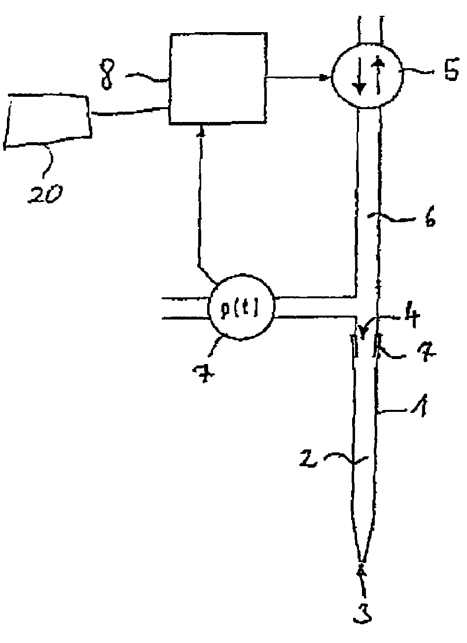
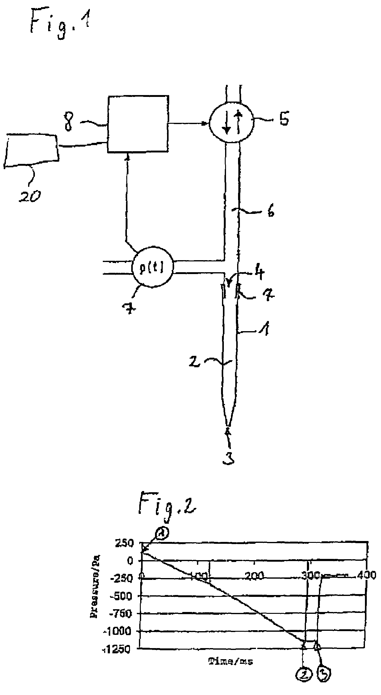
[0068]According to FIG. 1, the apparatus for dosing has a sample pickup portion 1, which is realised as a pipette point. The tube-like sample pickup portion 1 has a pickup volume 2 in the inside, a liquid passage 3 connecting the pickup volume with the surroundings on a bottom conical end and a gas passage that leads from the pickup volume 2 to the exterior, on a slightly conical extended upper end.

[0069]Further, there is a gas displacement system with a bidirectional pump 5, which is connected with a neck 7 for putting up the conical extended end of the sample pickup portion 1 via a connection channel6.

[0070]The pumping equipment 5 is for instance a (micro-) membrane pump, a ...


PUM

PropertyMeasurementUnit
volumeaaaaaaaaaa
pressureaaaaaaaaaa
working pointsaaaaaaaaaa

Abstract

Method for dosing liquid volumes, wherein a sample pickup portion with a pickup volume, the boundary of which is perforated with a liquid passage guiding to the outside and a gas passage, is dipped into a liquid with the liquid passage, a negative pressure is suddenly applied to the gas passage, which is generated by a gas displacement system, a drive of the gas displacement system is readjusted such that a constant negative working pressure exists in the sample pickup portion, the taken sample volume is detected with the aid of the readjusted driving path of the drive, the detected taken volume is compared with a predetermined value of the volume that is to be taken, when the predetermined value is reached by the taken volume, the negative pressure applied on the sample pickup portion is suddenly abated, the sample pickup portion with the liquid passage is pulled out of the liquid the sample pickup portion with the liquid passage is directed towards a releasing location, one ore more flow parameters is / are determined from the values of the taken volume, the negative working pressure and the time period required to take up the volume, an overpressure is applied to the gas passage of the sample pickup portion, the moment at which a volume that is to be released is released is determined with the aid of the flow parameter(s) and the overpressure, and when the moment is reached, the overpressure applied to the sample pickup portion is suddenly abated.

Description

CROSS-REFERENCE TO RELATED APPLICATIONS[0001]Not applicable.STATEMENT REGARDING FEDERALLY SPONSORED RESEARCH[0002]Not applicable.BACKGROUND OF THE INVENTION[0003]In known plunger stroke apparatuses, a gas cushion is moved by moving a plunger in a cylinder, in order to aspirate a liquid sample into a pipette point or another sample pickup portion or to eject it from it. The volume is determined with the aid of the volume displacement of the gas cushion, which is proportional to the adjusted path of the plunger. As an adjustment member or actor unit, respectively, for moving the plunger in the cylinder, a stepping motor is used for instance, which accurately hits working points for taking up and releasing liquid, in a fashion that is independent of the working load. After reaching the working points, it is waited until the taking or releasing of the liquid is complete. The dosing is based on the fact that pressure compensation up to reaching a static balance takes place between gas cu...

Claims


Application Information

Patent Timeline
Patent Type & Authority Patents(United States)
IPC IPC(8): G01N1/00
CPCG01N35/1016
Inventor SANDER, DIETMAR
Owner EPPENDORF SE
Why Eureka
Try Eureka