Air pump assembly for inflating and deflating an inflatable article

a technology of air pump and inflatable article, which is applied in the field of air pumps, can solve the problems of troublesome inflating process and troublesome process, and achieve the effect of easy operation of inflating

Inactive Publication Date: 2007-04-03
WU HSIN TSAI
View PDF5 Cites 24 Cited by
  • Summary
  • Abstract
  • Description
  • Claims
  • Application Information

AI Technical Summary

Benefits of technology

[0006]The object of this invention is to provide an air pump assembly that is disposed in an inflatable article and that can be operated easily to inflate and deflate the article.

Problems solved by technology

The process of removing the inflating equipment 14 from its separately stored location, then connecting the inflating equipment 14 to the air inlet valve 12 results in a troublesome inflating process.
This is also a troublesome process.

Method used


Image

  • Air pump assembly for inflating and deflating an inflatable article
  • Air pump assembly for inflating and deflating an inflatable article
  • Air pump assembly for inflating and deflating an inflatable article

Examples


Embodiment Construction

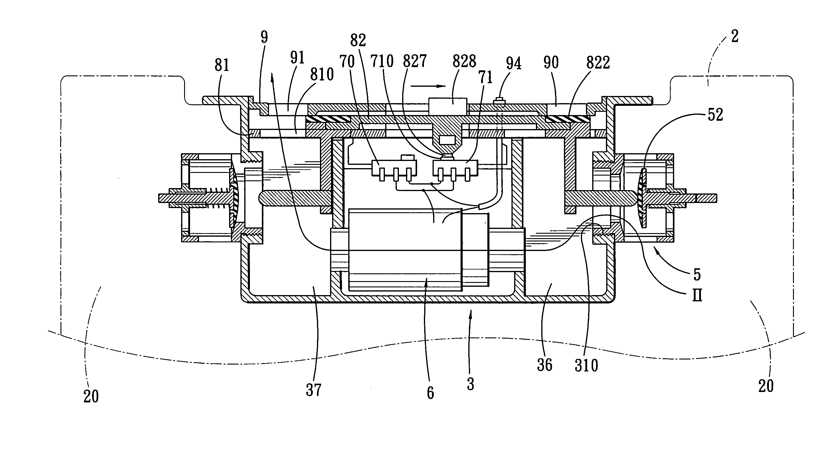
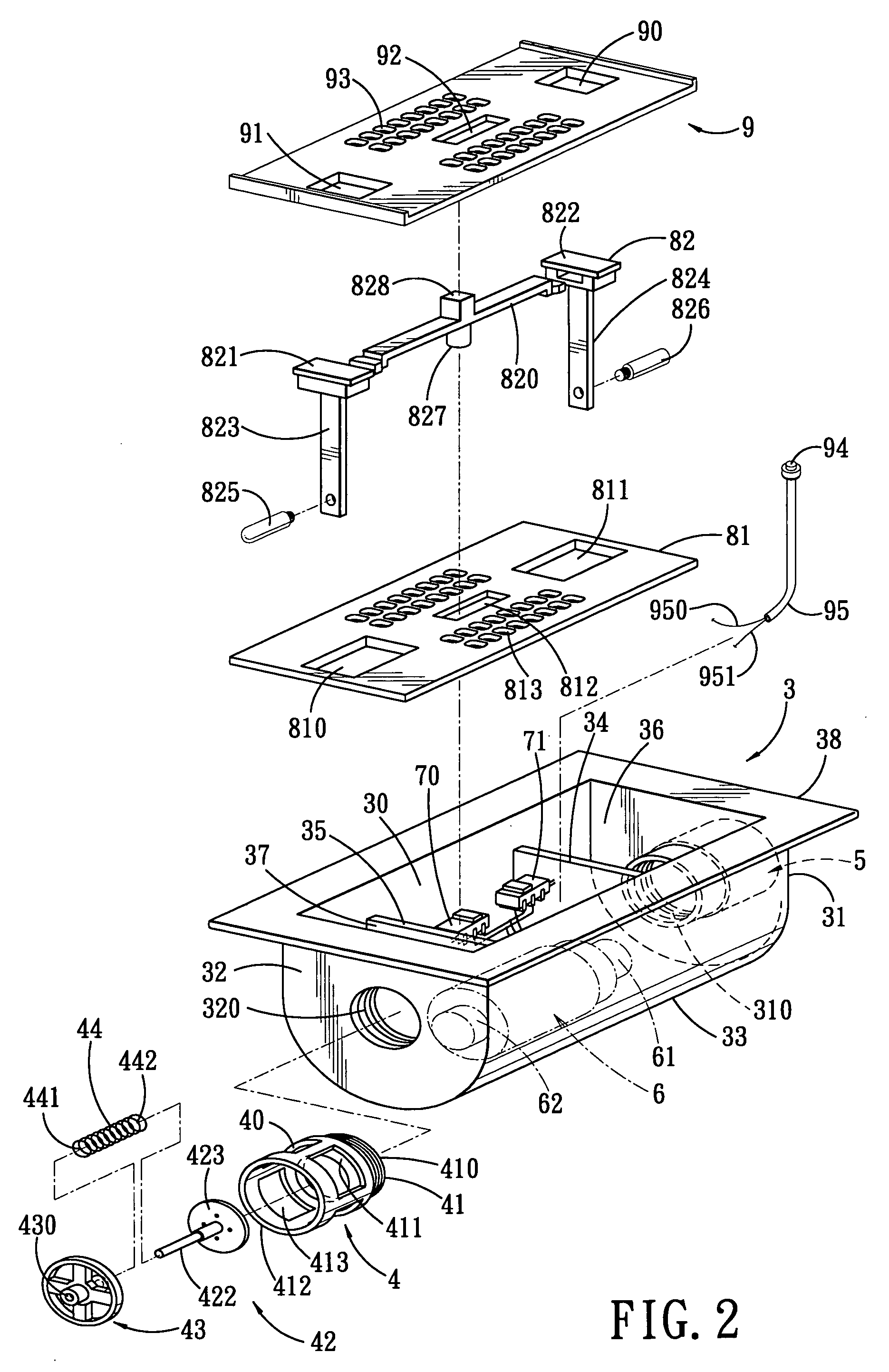
[0014]Referring to FIGS. 2 and 3, the preferred embodiment of an air pump assembly according to this invention is disposed in an inflatable article 2 (such as an inflatable bed), and is shown to include a base that includes a tub body 3, an inner plate 81 and an outer plate 9. The inflatable article 2 is formed with an interior chamber 20 and an aperture 21 in fluid communication with the interior chamber 20. The base is disposed within the aperture 21 in the inflatable article 2. The air pump assembly further includes an inflow valve assembly 4, an outflow valve assembly 5, an air pump 6, a control circuit 7 (see FIG. 3) and a movable member 82.

[0015]The tub body 3 includes a pair of opposite first and second end walls 31, 32 parallel to each other, and a U-shaped connecting wall 33 interconnecting the first and second end walls 31, 32 to define an accommodating chamber 30 among the first and second end walls 31, 32 and the connecting wall 33. A pair of parallel first and second pa...


PUM

PropertyMeasurementUnit
timeaaaaaaaaaa

Abstract

An air pump assembly is disposed within an inflatable article, and includes a movable member. When the movable member is moved relative to a base to an inflating position, an outflow outlet in the base is closed, and an inflow valve is activated to open an inflow outlet in the base so as to permit air to be sucked into the inflatable article through an inflow inlet and the inflow outlet in the base by an air pump. When the movable member is moved to a deflating position, the inflow inlet is closed, and an outflow valve is activated to open an outflow inlet in the base so as to permit air to be forced out of the inflatable article through the outflow inlet and the outflow outlet.

Description

CROSS-REFERENCE TO RELATED APPLICATION[0001]This application claims priority of Chinese Application No. 200420096575X, filed on Sep. 30, 2004.BACKGROUND OF THE INVENTION[0002]1. Field of the Invention[0003]This invention relates to an air pump, and more particularly to an air pump assembly for inflating and deflating an inflatable article.[0004]2. Description of the Related Art[0005]Referring to FIG. 1, a conventional inflatable bed 1 is shown to include an inflatable body 11, an air inlet valve 12 disposed at an end wall of the inflatable body 11 so as to allow for inflow of air therethrough, an air outlet valve 13 disposed at an opposite end wall of the inflatable body 11 so as to allow outflow of air therethrough. Inflating equipment 14 is connected to the air inlet valve 12 in order to inflate the bed 1. The process of removing the inflating equipment 14 from its separately stored location, then connecting the inflating equipment 14 to the air inlet valve 12 results in a trouble...

Claims


Application Information

Patent Timeline
Patent Type & Authority Patents(United States)
IPC IPC(8): B65B1/30A47C27/08F04D27/00
CPCA47C27/082F04D27/00F04D29/503F04D25/084
Inventor WU, HSIN-TSAI
Owner WU HSIN TSAI
Why Eureka
Try Eureka