
Enhanced electronic ink displays

a technology of electronic ink and display, applied in the field of displays, can solve the problems of time-consuming process and no easy way to replace labels, and achieve the effect of low cos

Inactive Publication Date: 2007-04-03
RAST RODGER H
View PDF1 Cites 23 Cited by
  • Summary
  • Abstract
  • Description
  • Claims
  • Application Information

AI Technical Summary

Benefits of technology

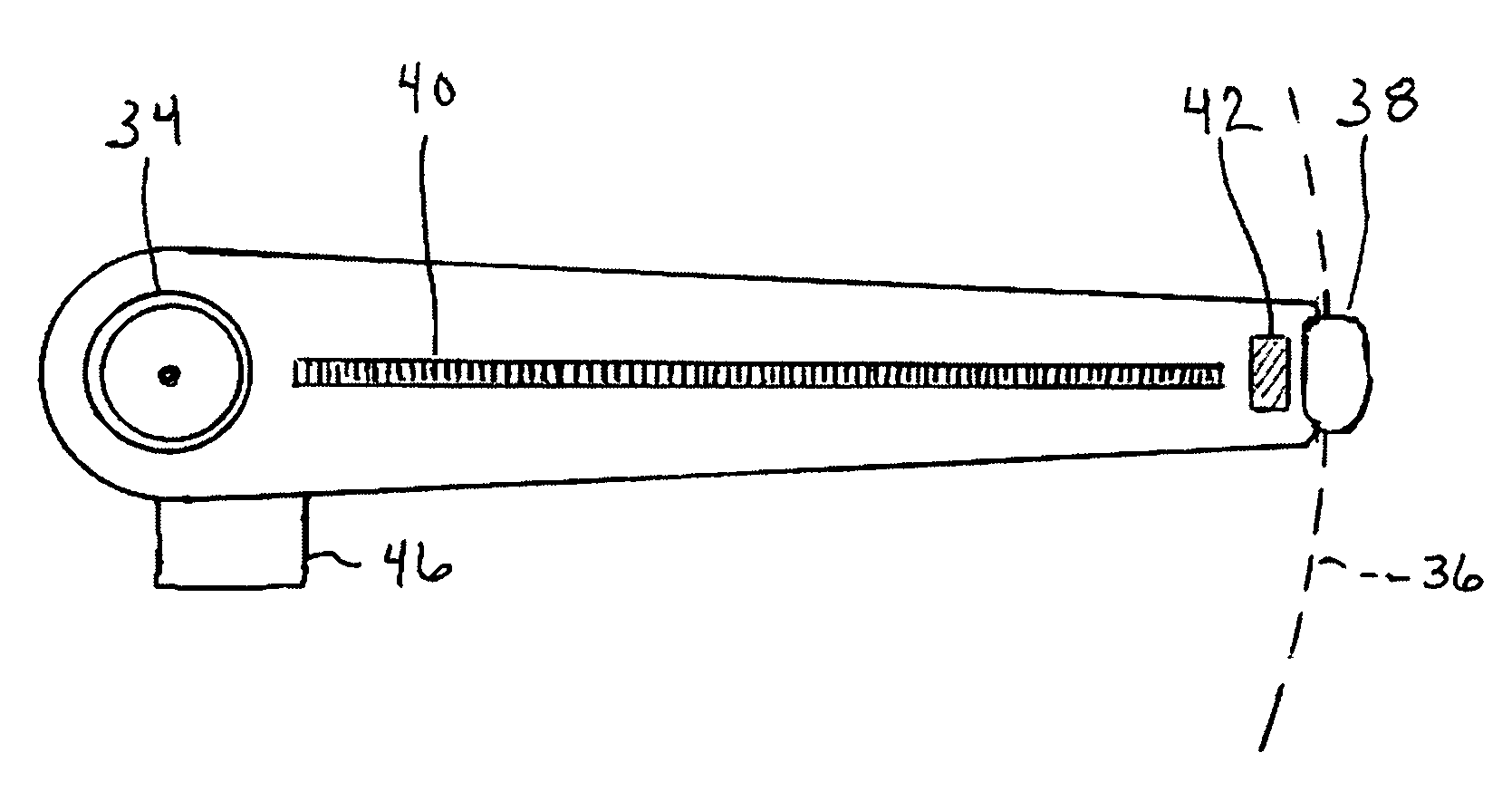
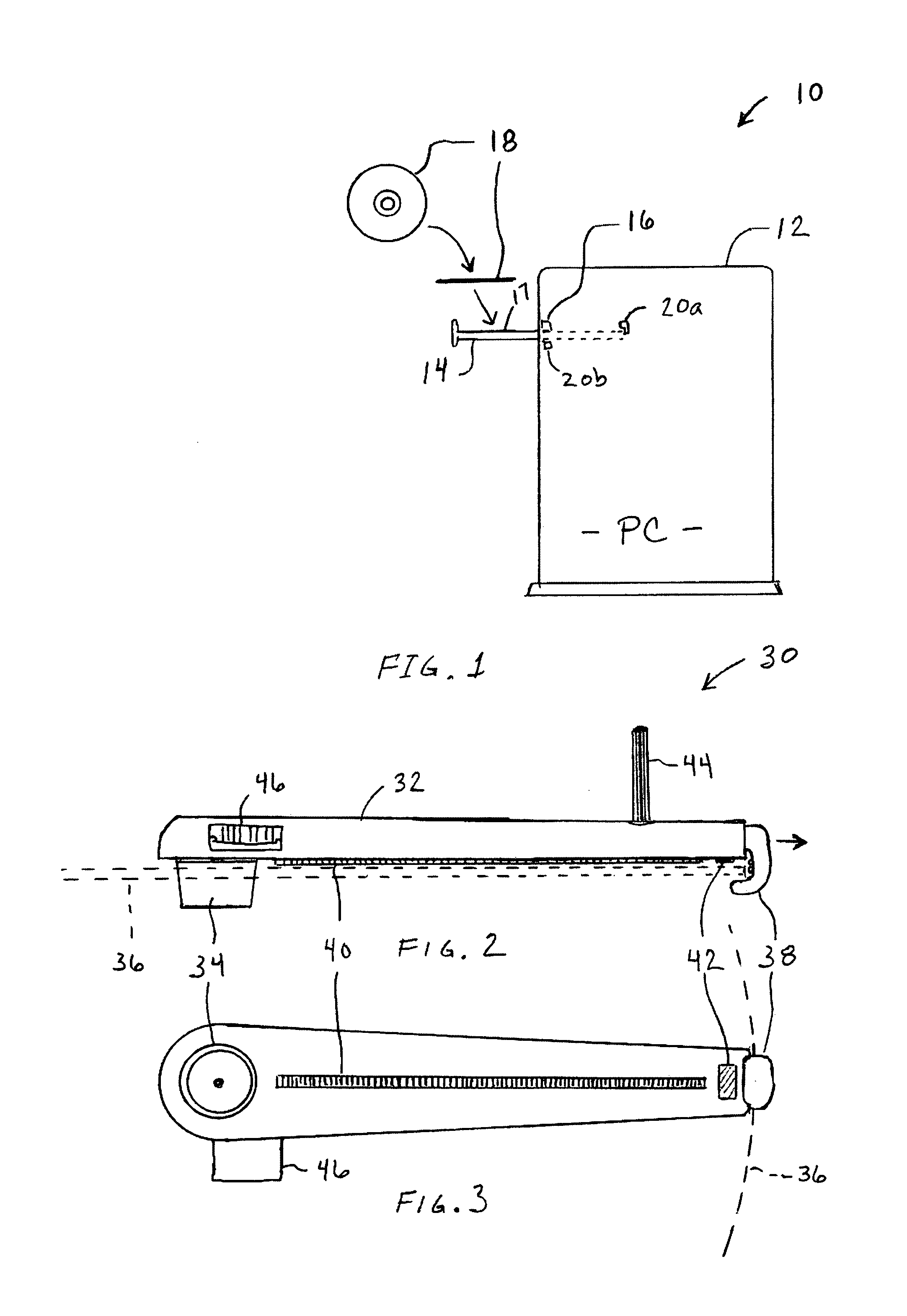
[0008]To provide a low cost method and system for marking Media. The system utilizes eInk, or another form of non-volatile display programmed with voltage field, retained on a media in combination with an electrode plane, that when utilized with a writing device containing a set of electrodes and a connection for the electrode plane allow setting the pixels of the eInk to a desired state, thus writing on the media. The media may be printed upon within a separate device, although the invention provides an apparatus wherein the media may be labeled when recorded or otherwise retained within a player.
[0010]An aspect of the invention is to provide a media which can be easily label with a rewritable label.
[0013]Another aspect of the invention is to provide a means of writing media that can be performed with an inexpensive and portable device.

Problems solved by technology

This process is time consuming and there is no easy way to replace the label with an updated one, especially when rewritable media is utilized.

Method used


Image

  • Enhanced electronic ink displays
  • Enhanced electronic ink displays
  • Enhanced electronic ink displays

Examples


embodiment 1

[0309]A three dimensional reflective laser stage is provided at the center of the device, preferably utilizing a number of MEMs mirrors for directing the light from the laser in a vector mode toward any desired position on the interior surface to write a message. The necessary speed of the laser can be reduced by layering phosphorescent material on the surface of the balloon, which keeps retains energy providing persistence between refreshes.

[0310]A single laser may then be used to save on power and weight requirements. The laser is modulated and the stage controlled so that messages may be written on the interior of the dirigible which are visible on the exterior of the unit. This unit may be similar in construction to the laser scan alarm described above, with both text and graphics may be displayed, even shades of gray by modulating the laser light at high speed to reduce effective intensity.

embodiment 2

n Dirigible—

[0311]A thin polymeric section of OLEDs can be incorporated into the exterior of the balloon for providing a display, these can be formed in multi-segment display areas so that less area need be covered, wherein the output may appear like balloon 2110 with segmented text 2112.

embodiment 3

Laser:

[0312]A simplified dirigible may be provided with graphics by generating a laser controlled on a three dimensional stage from a ground based location up to a surface of the dirigible. In order to display the message at the proper location on the dirigible the system incorporates means for locating said dirigible in three dimensions. The dirigible may be located optically, such as by processing the images received from an imager, such as CCD, directed toward the area of the sky where the dirigible is “posted”. The imager detects the edges of the dirigible and converts these to limits for the laser display head which then can “paint” the image on the center of the derisible. In this configuration it is preferred that the dirigible have a symmetrical cross section so that rotation due to wind will not alter the size or shape of the “screen” provided by the dirigible. Other forms of detection may also be utilized, such as a reflection sensor coupled to the laser generator itself w...


PUM


Abstract

An apparatus for rewritably labeling data media, such as compact disks CDs, DVDs, or other forms of media. The media may be programmed within a player / recorder device adapted for programming the state of the electronic ink material on the media. Labels on the media may be rewritten at any time without the need to remove a prior label. A small handheld label printing device is also described for writing the labels. Numerous other display embodiments particularly suited to electronic ink, and various embodiments of LED array control.

Description

CROSS-REFERENCE TO RELATED APPLICATIONS[0001]This application claims priority from U.S. provisional application Ser. No. 60 / 394,160 filed on Jul. 1, 2002.STATEMENT OF FEDERALLY SPONSORED RESEARCH OR DEVELOPMENT[0002]Not ApplicableREFERENCE TO A MICROFICHE APPENDIX[0003]Not ApplicableBACKGROUND OF THE INVENTION[0004]1. Field of the Invention[0005]This invention pertains generally to displays and more particularly to a method and system for labeling removable media.[0006]2. Description of the Background Art[0007]In order to mark media such as CDs, DVDs, tapes and the like, the user has been required in the past to purchase specialized labels, print the label such as on a printer, and then adhere the label to the media. This process is time consuming and there is no easy way to replace the label with an updated one, especially when rewritable media is utilized. The present system and method provides these capabilities.SUMMARY OF THE INVENTION[0008]To provide a low cost method and syste...

Claims


Application Information

Patent Timeline
IPC IPC(8): B41J3/00G09G5/00
CPCB41J3/4071B41J3/4076G09F3/00
Inventor RAST, RODGER H.
Owner RAST RODGER H
Learn More