Two-cycle engine

a two-cycle engine technology, applied in the direction of combustion engines, machines/engines, feed systems, etc., can solve the problems of affecting the quality of exhaust gas emissions, achieve the effects of reducing the flow cross-section, improving the drawing-in of fuel, and being easy and economical to manufactur

Inactive Publication Date: 2007-04-10
ANDREAS STIHL AG & CO KG
View PDF1 Cites 9 Cited by
  • Summary
  • Abstract
  • Description
  • Claims
  • Application Information

AI Technical Summary

Benefits of technology

[0010]The two-cycle engine of the present application comprises a cylinder having a combustion chamber formed therein; a piston reciprocably mounted in the cylinder, wherein in prescribed positions of the piston the combustion chamber is in communication with a crankcase via at least one transfer channel; an intake channel for supplying fuel / air mixture and combustion air; a carburetor, wherein a portion of the intake channel is formed in the carburetor; a butterfly valve pivotably mounted in the carburetor for controlling the flow cross-section of the intake channel, wherein a fuel opening opens into the intake channel portion, and wherein downstream of the carburetor the intake channel is divided into a mixture channel and an air channel; and means disposed on the butterfly valve for increasing the speed of flow in the carburetor in the vicinity of the fuel opening.
[0011]Due to the increase of the speed or velocity of flow in the region of the fuel opening, the fuel is supplied to the two-cycle engine via the mixture channel. A passage of fuel into the air channel can thereby be substantially avoided.
[0013]A flow-directing element on the butterfly valve leads to an alteration of the flow when the butterfly valve is completely opened. As a result, it is possible to influence the flow in that section of the intake channel that is disposed upstream of the mixture channel and into which the fuel opening opens. The flow-directing element can be embodied in such a way that the flow is accelerated at the fuel opening, thus ensuring an adequate supply of fuel.
[0014]The flow-directing element is disposed on a that portion of the butterfly valve that is disposed upstream of the throttle shaft when the butterfly valve is completely opened. As a result, the flow-directing element can influence the flow in the region of the fuel opening, whereas downstream of the throttle shaft there is substantially no influence upon the flow. The flow-directing element preferably reduces the flow cross-section in the intake channel. This results in an acceleration of the flow, which leads to an improved drawing-in of fuel from the fuel opening. However, the flow-directing element can also be disposed on that portion of the butterfly valve that is disposed downstream of the throttle shaft when the butterfly valve is completely opened. The flow-directing element is in particular secured to the butterfly valve. In this connection, the flow-directing element can be clipped onto the butterfly valve or screwed or otherwise secured to the throttle shaft. However, it can also be advantageous to monolithically form the flow-directing element with the butterfly valve. The flow-directing element is preferably made of polymeric material, in which case the surface of the element that influences the flow can have substantially any shape. A flow-directing element made of polymeric material is easy and economical to manufacture, and brings about an only minimal increase in the weight of the two-cycle engine.
[0016]A straightforward configuration of the two-cycle engine results if the intake channel is divided by a partition into an air channel and a mixture channel. One end of the partition is disposed at the downstream end face of the carburetor. The partition does not extend into the carburetor housing, but rather ends essentially at the end face of the carburetor. In this way, guide means for the partition in the interior of the carburetor can be eliminated, so that a conventional carburetor can be utilized. To influence the flow distribution between air channel and mixture channel, a narrowed section is formed in the carburetor in a section of the intake channel that is disposed upstream of the air channel. The narrowed section is preferably disposed approximately at the level of the butterfly valve. The narrowed section is in particular formed by the venturi section. However, the venturi section can also extend in the carburetor only in that section of the intake channel that is disposed upstream of the mixture channel, while a narrowed section that is separate from the venturi section is disposed in the carburetor in that section of the intake channel that is disposed upstream of the air channel. In this connection, the narrowed section can also be disposed on the butterfly valve.

Problems solved by technology

The fuel that passes into the combustion chamber through the air channel can escape out of the combustion chamber with the exhaust gases, thus impairing the quality of the exhaust gas emissions.

Method used


Image

  • Two-cycle engine
  • Two-cycle engine
  • Two-cycle engine

Examples


Embodiment Construction

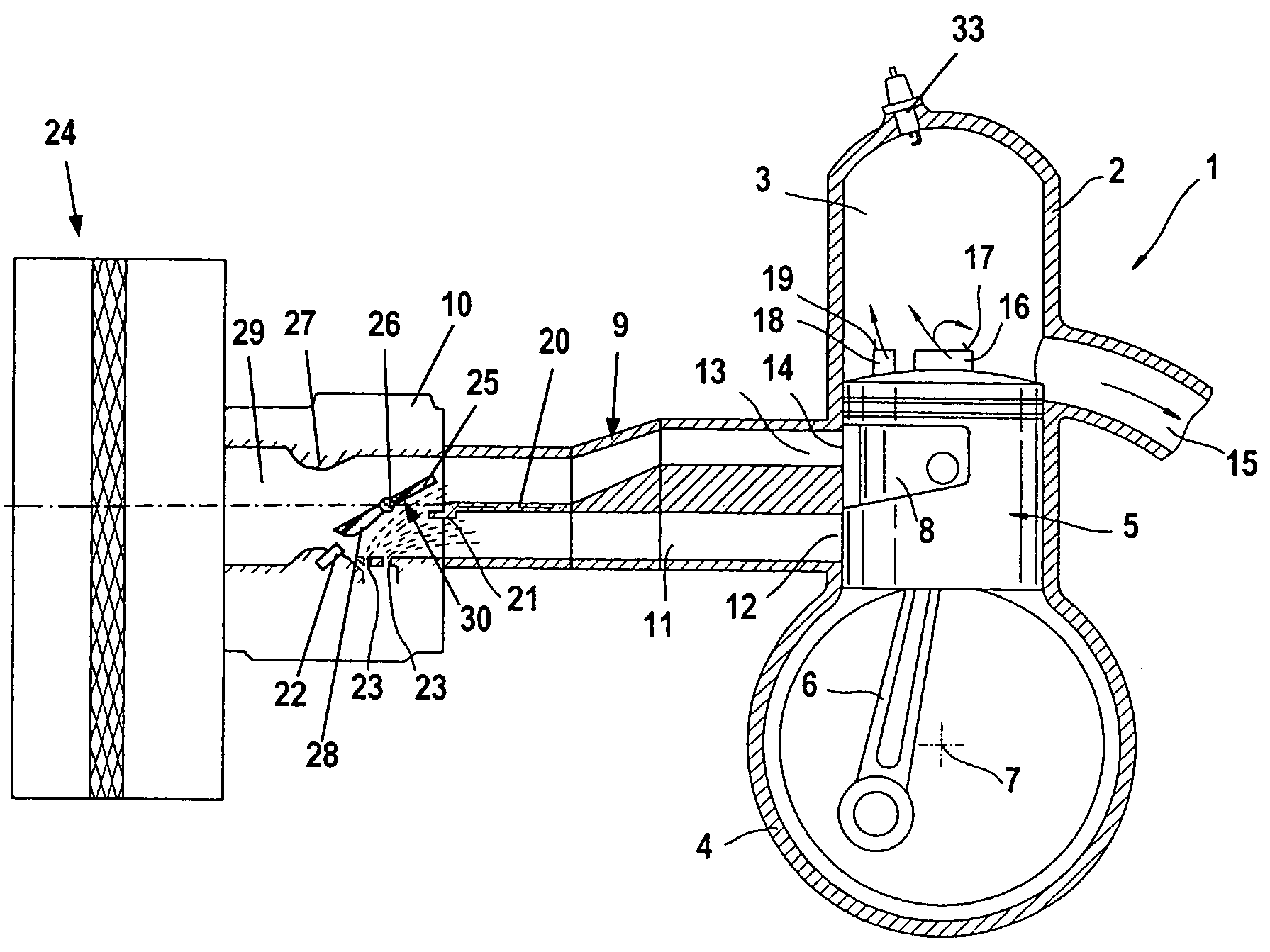
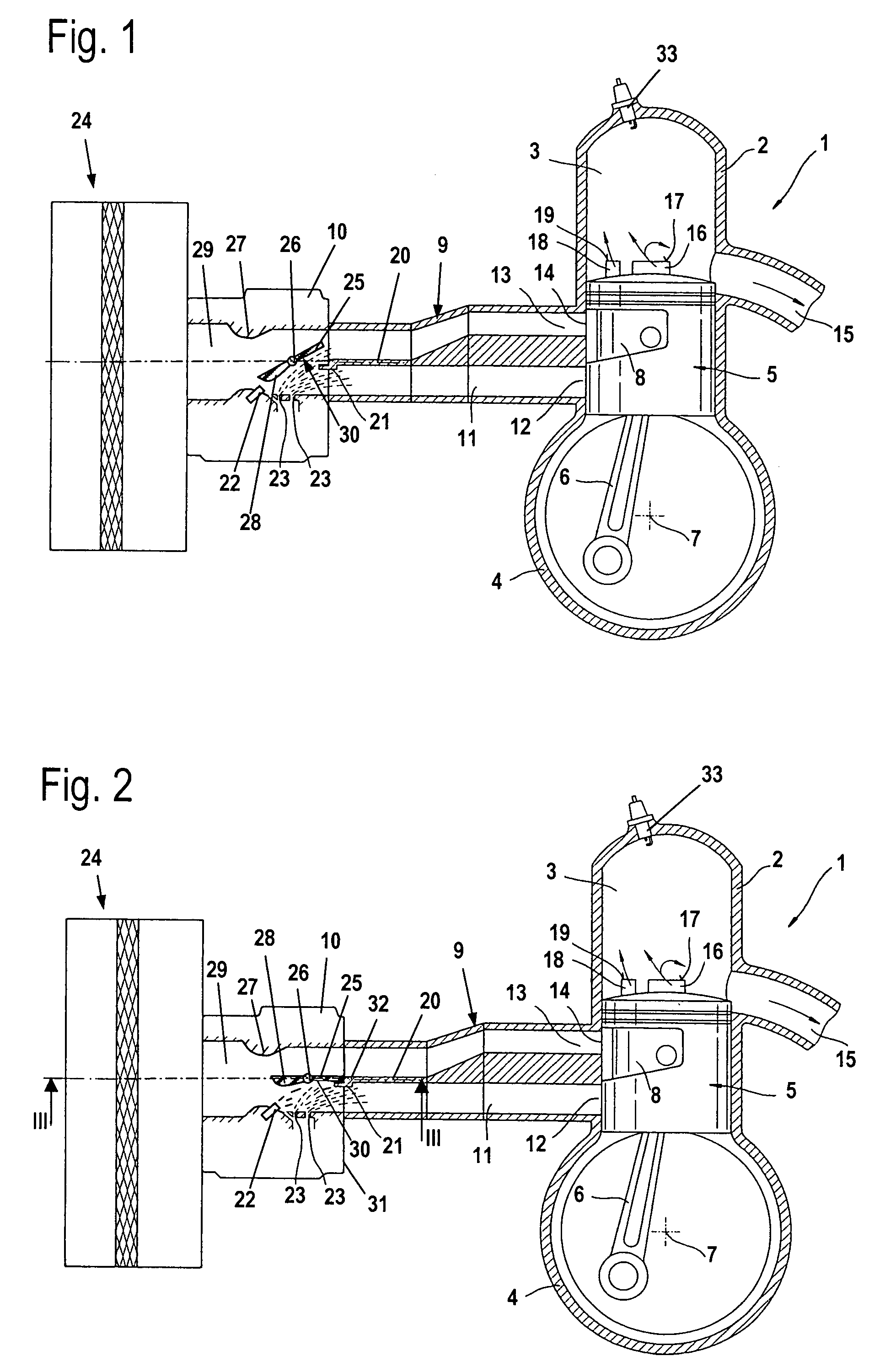
[0018]Referring now to the drawings in detail, the two-cycle engine 1 shown in FIG. 1 is embodied as a crankcase scavenging two-cycle engine, and preferably is provided for installation in a manually-guided implement such as a power saw, a cut-off machine, a brush cutter, or the like. The two-cycle engine 1 has a cylinder 2 in which is formed a combustion chamber 3, which is delimited by a piston 5 that is reciprocably mounted in the cylinder 2. By means of a connecting rod 6, the piston 5 drives a crankshaft 7 that is rotatably mounted in a crankcase 4. The crankshaft 7 preferably drives the tool of the implement. In the region of the lower dead center point of the piston 5 shown in FIG. 1, the crankcase 4 communicates with the combustion chamber 3 via two transfer channels 16 and two transfer channels 18. One transfer channel 16 and one transfer channel 18 are disposed in front of the drawing plane of FIG. 1 and are therefore not illustrated. The transfer channels 16 and 18 open v...


PUM


Abstract

A two-cycle engine having a piston reciprocalbly mounted in a cylinder in which a combustion chamber is formed. In prescribed positions of the piston, the combustion chamber communicates with a crankcase via at least one transfer channel. A portion of an intake channel for supplying fuel / air mixture and combustion air is formed in a carburetor, in which is pivotably mounted a butterfly valve for controlling the flow cross-section of the intake channel. A fuel opening opens into the intake channel portion, and downstream of the carburetor the intake channel is divided into a mixture channel and an air channel. A mechanism is disposed on the butterfly valve to increase the speed of flow in the carburetor in the vicinity of the fuel opening.

Description

[0001]The instant application should be granted the priority date of Apr. 2, 2005, the filing date of the corresponding German patent application 10 2005 015 164.7.BACKGROUND OF THE INVENTION[0002]The present invention relates to a two-cycle engine, especially one in a manually-guided implement such as a power saw, a brush cutter, a cut-off machine, or the like.[0003]U.S. Pat. No. 6,101,991 discloses a two-cycle engine having an intake duct or channel that is divided into an air channel and a mixture channel. The two-cycle engine has a carburetor in which a butterfly valve is pivotably mounted in a portion of the intake channel. In the completely opened position, the butterfly valve rests against the edge of a ring-shaped element. Downstream of the throttle shaft, a partition that divides the intake channel adjoins the ring-shaped element. Opening into the intake channel is a fuel opening that upstream of the butterfly valve is disposed at a level to which the ring-shaped element ju...

Claims


Application Information

Patent Timeline
Patent Type & Authority Patents(United States)
IPC IPC(8): F02B33/04
CPCF02B25/22F02B33/04F02M9/08Y10S261/52Y10S261/12
Inventor GEYER, WERNERZURCHER, LUKAS
Owner ANDREAS STIHL AG & CO KG
Why Eureka
Try Eureka