Controlled mode conversion connector for reduced alien crosstalk

a technology of conversion connector and controlled mode, which is applied in the direction of coupling device connection, two-part coupling device, electrical apparatus, etc., can solve the problems of not being able to meet the requirements of high-speed data transmission, the accepted level of crosstalk of the “nominal plug,” in particular for the pair 1-pair 3 combination, and the inability to pick up electrical noise. to achieve the effect of reducing alien crosstalk

Active Publication Date: 2007-04-10
COMMSCOPE INC
View PDF80 Cites 122 Cited by
  • Summary
  • Abstract
  • Description
  • Claims
  • Application Information

AI Technical Summary

Benefits of technology

[0016]As a first aspect, embodiments of the present invention are directed to a telecommunications connector. The connector comprises first and second pairs of electrical conductors. The first and second pairs of conductors are arranged in one region of the connector such that one conductor of the first pair is selectively positioned to be closer to both of the conductors of the second pair than is the other conductor of the first pair, and such that the one conductor of the first pair couples a common mode signal of a first polarity onto the conductors of the second pair. In another region of the connector the other conductor of the first pair is selectively positioned to be closer to both of the conductors of the second pair to couple a common mode signal of a second polarity onto the conductors of the second pair. In this configuration, the connector (in some embodiments a communications plug) can reduce alien crosstalk.
[0020]As a fifth aspect, embodiments of the present invention are directed to a method of controlling the signal being output by a communications plug when a balanced signal is applied, comprising: positioning a first pair of conductors relative to a dielectric substrate; positioning a second pair of conductors relative to a dielectric substrate; positioning a third pair of conductors relative to a dielectric substrate; and positioning a fourth pair of conductors relative to a dielectric substrate. The positions of the first, second, third and fourth pairs of conductors are selected to control differential to common mode coupling between the conductors to counteract the effects of cross-modal coupling that would otherwise exist between the conductors.

Problems solved by technology

Each wire in a wire-pair is susceptible to picking up electrical noise from sources such as lightning, automobile spark plugs, and radio stations, to name but a few.
Of greater concern, however, is the electrical noise that is picked up from nearby wires or pairs of wires that may extend in the same general direction for some distances and not cancel differentially on the victim pair.
These requirements are not necessarily optimum for high speed data transmission.
The accepted levels of crosstalk for a “Nominal Plug,” in particular for the Pair 1-Pair 3 combination, are fairly restrictive.
However, with the new standards and high data rates that are evolving, this is no longer true.
Since the newly defined alien crosstalk can be generated from any unrelated data transmission, it can be difficult to use current signal processing techniques to calculate and subtract away their effects within a four-pair cable connection (referred to as a “port”).
Another issue with alien crosstalk results from the fact that alien crosstalk levels vary based on a number of random factors such as how adjacent cables are bundled together, the physical proximity of the plugs and jacks within a given system, the number of cables adjacent to each other, and the like.
As a result of these factors, the degree to which alien crosstalk can be “corrected” for is limited, and alien crosstalk can ultimately dominate the final system performance levels.
For a two-conductor transmission line, increasing the separation between conductors generally causes the field patterns to become more spread out, which can result in increased levels of crosstalk for a fixed physical separation between cables.
This physical structure does not maintain symmetry between the four pairs internal to a cable.
Although shielding can be an effective solution to alien crosstalk, it is not consistent with an unshielded twisted pair installation base and is typically more expensive to manufacture and install.

Method used


Image

  • Controlled mode conversion connector for reduced alien crosstalk
  • Controlled mode conversion connector for reduced alien crosstalk
  • Controlled mode conversion connector for reduced alien crosstalk

Examples


example

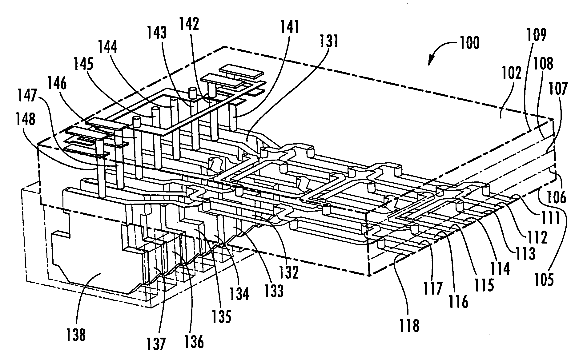
[0075]A “conventional” Nominal Plug was modeled using HFSS Finite Element software, available from Ansoft Corporation. In addition, a “balanced” plug of the configuration illustrated in FIGS. 4A–5B above was also modeled. Mixed mode analysis was then performed on the conventional and balanced plugs.

[0076]The results from the mixed mode analysis are shown in FIG. 6 (the curves for Pair 3-2 and Pair 3-4 were identical for the conventional plug; hence, only one curve is visible in FIG. 6; it represents both pair combinations). As can be seen from the curves of FIG. 6, the inclusion of compensating inductive and capacitive crosstalk in the balanced plug significantly reduced the degree of mode conversion for both pair combinations compared to that of a conventional plug, particularly at elevated frequencies. Consequently, a plug of this configuration should produce less crosstalk to a mating jack, which can reduce the degree of compensation necessary in the jack for desired performance....


PUM


Abstract

A telecommunications connector includes first and second pairs of electrical conductors. The first and second pairs of conductors are arranged in one region of the connector such that one conductor of the first pair is selectively positioned to be closer to both of the conductors of the second pair than is the other conductor of the first pair, and such that the one conductor of the first pair couples a common mode signal of a first polarity onto the conductors of the second pair. In another region of the connector the other conductor of the first pair is selectively positioned to be closer to both of the conductors of the second pair to asymmetrically couple a common mode signal of a second polarity onto the conductors of the second pair.

Description

RELATED APPLICATIONS[0001]This application claims priority from U.S. Provisional Patent Application Ser. No. 60 / 648,002, filed Jan. 28, 2005, entitled CONTROLLED MODE CONVERSION PLUG FOR REDUCED ALIEN CROSSTALK and U.S. patent application Ser. No. 11 / 051,305, filed Feb. 4, 2005 the disclosures of each of which are hereby incorporated herein by reference, in their entireties.FIELD OF THE INVENTION[0002]The present invention relates generally to communication connectors and more particularly to near-end crosstalk (NEXT) and far-end crosstalk (FEXT) compensation in communication connectors.BACKGROUND OF THE INVENTION[0003]In an electrical communication system, it is sometimes advantageous to transmit information signals (e.g., video, audio, data) over a pair of wires (hereinafter “wire-pair” or “differential pair”) rather than a single wire, wherein the transmitted signal comprises the voltage difference between the wires without regard to the absolute voltages present. Each wire in a ...

Claims


Application Information

Patent Timeline
Patent Type & Authority Patents(United States)
IPC IPC(8): H01R24/00
CPCH01R13/6477H01R13/6658Y10S439/941H01R24/64H01R13/6466H01R13/6469
Inventor ELLIS, THOMASLARSEN, WAYNEHASHIM, AMID I.PHARNEY, JULIAN
Owner COMMSCOPE INC
Why Eureka
Try Eureka