High efficiency power converter

a power converter and high efficiency technology, applied in the direction of electric variable regulation, process and machine control, instruments, etc., can solve the problems of reducing the overall efficiency of the two-stage power converter, the tendency of the battery to gradually decrease the voltage, etc., and achieve the effect of improving the efficiency of power conversion and high efficiency

Inactive Publication Date: 2007-04-10
RICHTEK TECH
View PDF2 Cites 1212 Cited by
  • Summary
  • Abstract
  • Description
  • Claims
  • Application Information

AI Technical Summary

Benefits of technology

[0006]In a high efficiency power converter, according to the present invention, a boost converter is used to convert an input voltage to a first voltage on a first output, a buck converter is used to convert the input voltage to a second voltage on a second output, and a linear regulator is coupled between the first and second outputs to convert the first voltage to a third voltage on the second output when the second voltage is lower than a first threshold. The buck converter comprises a switch coupled between the input voltage and the second output, an error amplifier for generating an error signal in response to a difference between the voltage on the second output and a reference voltage, and a logic circuit responsive to the error signal for switching the switch. A voltage detector is further comprised in the power converter to detect the input voltage, so as to prevent a reverse current flowing from the second output to the buck converter when the input voltage is lower than a second threshold.
[0007]Since the power conversion is implemented by single conversion stage, either with the boost converter or with the buck converter, in association with the linear regulator to generate the third voltage in replace of the second voltage when the second voltage is lower than the first threshold, the overall efficiency of the power conversion is improved up to about 90% or more.

Problems solved by technology

However, the battery has a tendency of gradually decreased voltage as the use time increases.
Namely, the overall efficiency of the two-stage power converter is reduced due to the cascaded conversion.

Method used


Image

  • High efficiency power converter
  • High efficiency power converter
  • High efficiency power converter

Examples


Embodiment Construction

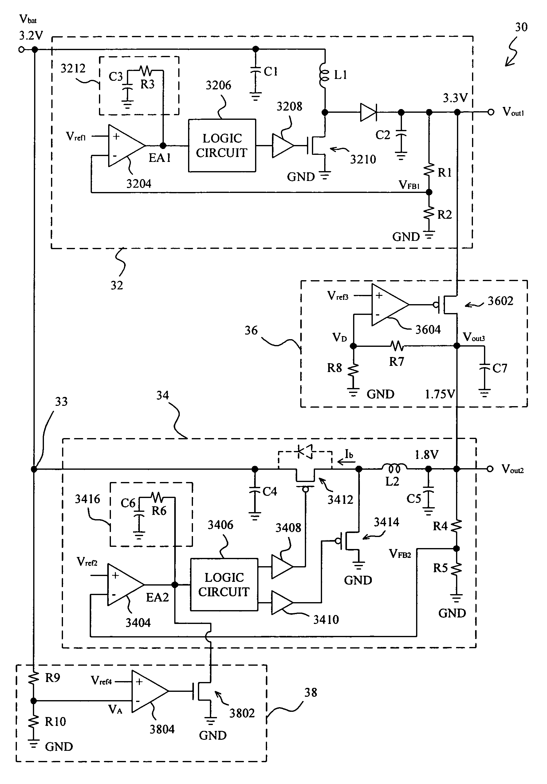
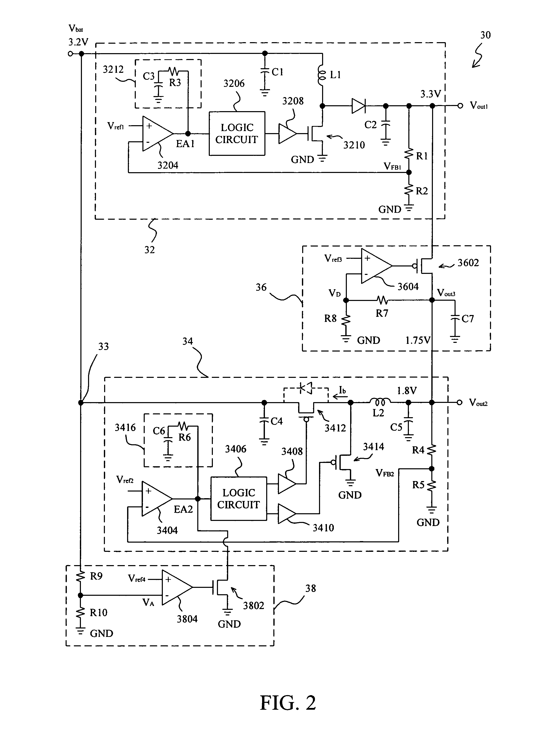
[0012]FIG. 2 shows a power converter 30, according to the present invention, that uses two alkaline batteries as its power source. In the power converter 30, the input voltage Vbat supplied by the two alkaline batteries is 3.2V, and is converted by a boost converter 32 to generate a first voltage of 3.3V on a first output Vout1. The level of the first voltage Vout1 is set up by selecting the parameters of the inductor L1, capacitors C1 and C2, and resistors R1 and R2 in the boost converter 32. In the boost converter 32, the resistors R1 and R2 connected in series between the first output Vout1 and ground GND serve as a voltage divider for dividing the first voltage Vout1 to generate a feedback voltage VFB1 for an error amplifier 3204 to compare with a reference voltage Vref1, so as to generate an error signal EA1 upon which a logic circuit 3206 will generate a signal to switch a transistor 3210 by a driver 3208 to regulate the first voltage Vout1 at 3.3V. The error signal EA1 may be...


PUM


Abstract

A high efficiency power converter comprises a boost converter for converting an input voltage to a first voltage on a first output, a buck converter for converting the input voltage to a second voltage on a second output, a linear regulator for converting the first voltage to a third voltage on the second output when the second voltage is lower than a first threshold, and a voltage detector for detecting the input voltage for preventing a reverse current flowing from the second output to the buck converter when the input voltage is lower than a second threshold.

Description

FIELD OF THE INVENTION[0001]The present invention is related generally to power conversion and more particularly, to a high efficiency power converter.BACKGROUND OF THE INVENTION[0002]For portable electronic products, alkaline and lithium batteries are generally used as the power sources. However, the battery has a tendency of gradually decreased voltage as the use time increases. To retain a stable output voltage, a two-stage power converter is typically employed, by which the input voltage supplied by the battery or batteries is stepped up first and then stepped down to the desired level.[0003]FIG. 1 shows a conventional two-stage power converter 10, which comprises a boost converter 12 cascaded with a buck converter 14. Generally, the battery voltage Vbat is provided by two alkaline batteries or one lithium battery. The battery voltage Vbat is converted by the boost converter 12 to generate a first output voltage Vout1, and then the first output voltage Vout1 is converted by the ...

Claims


Application Information

Patent Timeline
Patent Type & Authority Patents(United States)
IPC IPC(8): G05F1/40H02M3/00H02M3/156H02M3/335
CPCH02M3/156H02M2001/008H02M2001/007H02M2001/0045H02M1/0045H02M1/008H02M1/007
Inventor PAI, CHUNG-LUNG
Owner RICHTEK TECH
Why Eureka
Try Eureka