
Drowsiness detection system and method

a detection system and drowsiness technology, applied in the field of eye monitoring, can solve problems such as the general cost of techniques

Inactive Publication Date: 2007-04-10
APTIV TECH LTD
View PDF10 Cites 70 Cited by
  • Summary
  • Abstract
  • Description
  • Claims
  • Application Information

AI Technical Summary

Benefits of technology

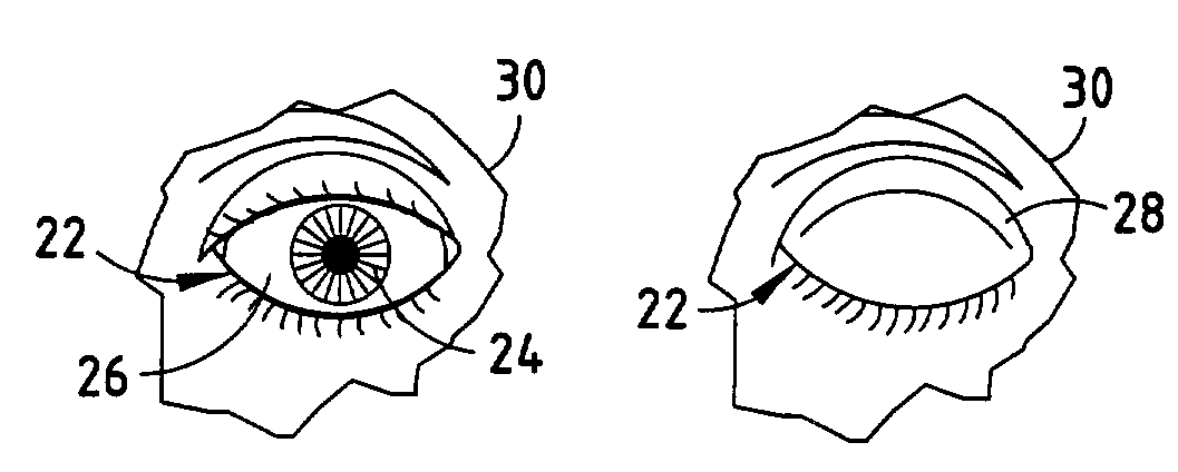
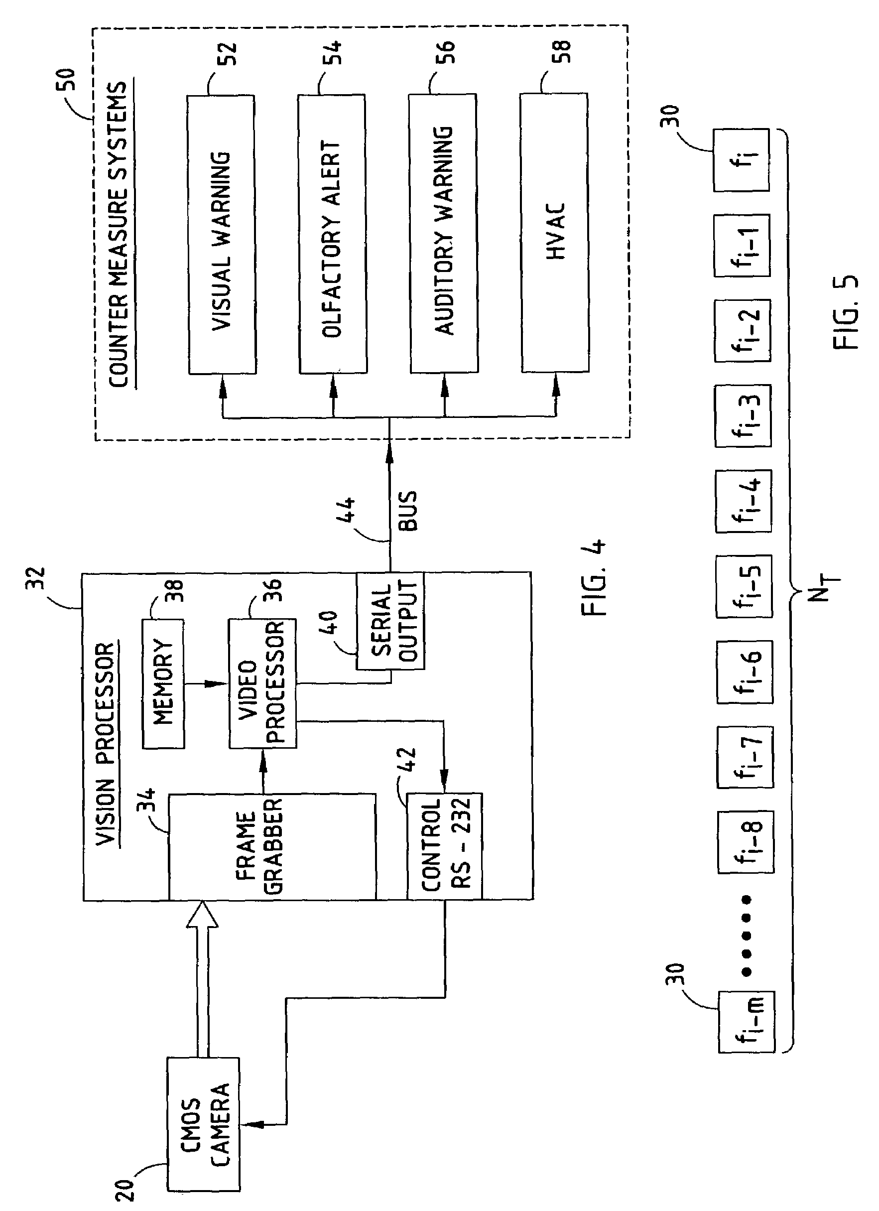
[0005]The present invention provides for a low-cost system for detecting a drowsy condition by monitoring a person's eye. The system includes a video imaging camera oriented to generate images of a person, including an eye. The system also includes a processor for processing the images generated by the video imaging camera. The processor monitors the acquired image and determines whether the eye is in one of an open position and a closed position. The processor further determines a time proportion of eye closure as the proportion of a time interval that the eye is in the closed position, and determines a drowsiness condition when the time proportion exceeds a threshold value.
[0006]According to one aspect of the present invention, the camera is located in a vehicle for monitoring the eye of the driver of the vehicle, and the system determines a driver drowsy condition. According to a further aspect of the present invention, the processor may further output a signal indicative of the determined driver drowsiness condition so as to initiate a countermeasure, such as provide a visual or audible alarm or to adjust temperature in the vehicle so as to mitigate the driver drowsy condition.

Problems solved by technology

Many vehicle accidents are caused by the driver of the vehicle becoming drowsy and then falling asleep.
While the aforementioned proposed technique is able to use the percent of closure of the eye of the driver as an indicator of driver drowsiness, such a technique is generally costly.

Method used


Image

  • Drowsiness detection system and method
  • Drowsiness detection system and method
  • Drowsiness detection system and method

Examples


Embodiment Construction

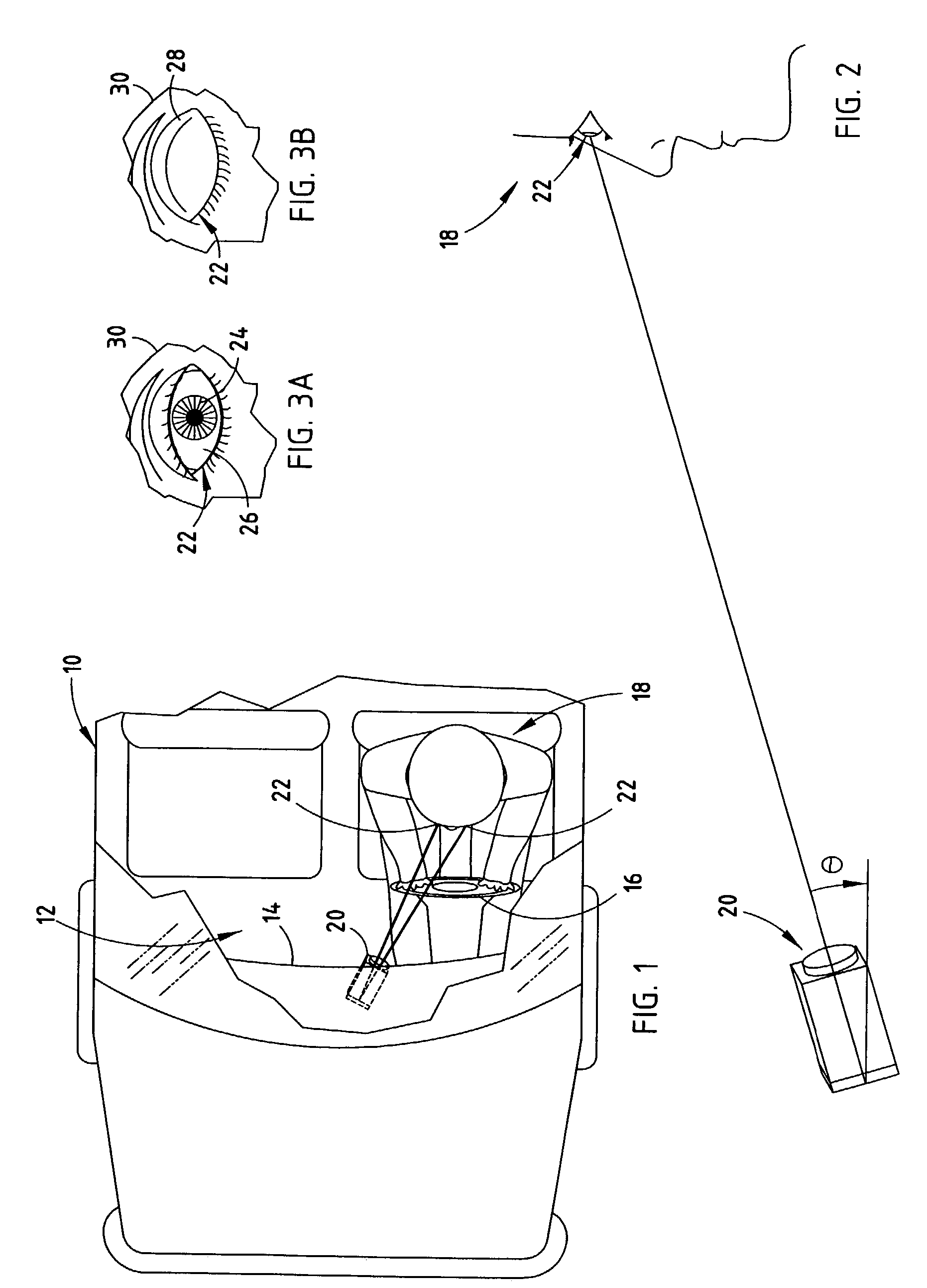
[0015]Referring now to FIG. 1, the passenger compartment (cockpit) 12 of a vehicle 10 is generally shown equipped with a mono-camera driver drowsiness detector system having a video imaging camera 20 located within the dash 14 and focused on the person (driver) 18 driving the vehicle 10 for generating images of the driver 18. The video imaging camera 20 is shown mounted generally in a mid-region of the dash in the front region of the cockpit 12. The video imaging camera 20 may be mounted in any of a number of various locations within the vehicle 10 which allow for the acquisition of video images of one or both eyes of the driver 18 of the vehicle 10. For example, the video imaging camera 20 may be mounted in the steering assembly 16, or mounted elsewhere in the dash 14, or may be mounted in the instrument cluster as disclosed in U.S. application Ser. No. 10 / 103,202, filed on Mar. 21, 2002, the entire disclosure of which is hereby incorporated herein by reference. While a single vide...


PUM


Abstract

A low-cost system for detecting a drowsy condition of a driver of a vehicle includes a video imaging camera located in the vehicle and oriented to generate images of a driver of the vehicle. The system also includes a processor for processing the images acquired by the video imaging camera. The processor monitors an eye and determines whether the eye is in an open position or a closed state. The processor further determines a time proportion of eye closure as the proportion of a time interval that the eye is in the closed position, and determines a driver drowsiness condition when the time proportion of eye closure exceeds a threshold value.

Description

TECHNICAL FIELD[0001]The present invention generally relates to eye monitoring and, more particularly, relates to detecting a drowsiness condition of a person, particularly a driver of a vehicle, by monitoring one or both eyes with a video imaging system.BACKGROUND OF THE INVENTION[0002]Video imaging systems have been proposed for use in vehicles to monitor the driver and / or passengers in the vehicle. Some proposed imaging systems include one or two cameras focused on the driver of the vehicle to capture images of the driver's face and allow for determination of various facial characteristics of the driver including the position, orientation, and movement of the driver's eyes, face, and head. By knowing the driver facial characteristics, such as the driver's eye position and gaze, ocular data, head position, and other characteristics, vehicle control systems can provide enhanced vehicle functions. For example, a vehicle control system can monitor the eye of the driver and determine ...

Claims


Application Information

Patent Timeline
IPC IPC(8): G08B23/00B60K28/06G08B21/06
CPCB60K28/066G08B21/06
Inventor ZHANG, HARRYWITT, GERALD J.SMITH, MATTHEW R.
Owner APTIV TECH LTD
Learn More