Print layout apparatus and method

a technology of printing layout and printing apparatus, which is applied in the direction of digital output to print units, visual presentation using printers, instruments, etc., can solve the problems of unnatural printing, difficult to recognize all combinations of combinations on the information processing apparatus side, and strong restrictions on processes

Active Publication Date: 2007-04-10
CANON KK
View PDF15 Cites 10 Cited by
  • Summary
  • Abstract
  • Description
  • Claims
  • Application Information

AI Technical Summary

Benefits of technology

[0010]Accordingly, it is an object of the present invention to minimize any change that print data falls outside the effective print range when a binding margin is processed on the printing apparatus side.
[0013]According to the second aspect of the present invention, when a plurality of pages with different sizes or different print directions of paper sheets are mixed, some possible combinations of binding margin positions are displayed, one of the displayed combinations is designated, and the margin amount is set on the basis of the designated combination. Since the user can visually recognize possible combinations of binding margin positions when a plurality of pages with different sizes or different print directions of paper sheets are mixed, difficulty in designation of the binding margin position can be relaxed.

Problems solved by technology

Normally, since print data which falls outside the effective print range is not printed, only an unnatural print result like a partial image can be obtained.
Such processes are also strongly restricted by a printing apparatus and paper feed and exhaust mechanisms attached to that apparatus.
Since there are a wide variety of characteristics of printing apparatuses, and also a wide variety of ways in which the margin is used, it is very difficult to recognize all combinations of them on the information processing apparatus side, and to appropriately form a margin by only a process on the information processing apparatus side.
The user cannot recognize the actual binding method, and can hardly image an output result in association with the binding margin setup.

Method used


Image

  • Print layout apparatus and method
  • Print layout apparatus and method
  • Print layout apparatus and method

Examples


first embodiment

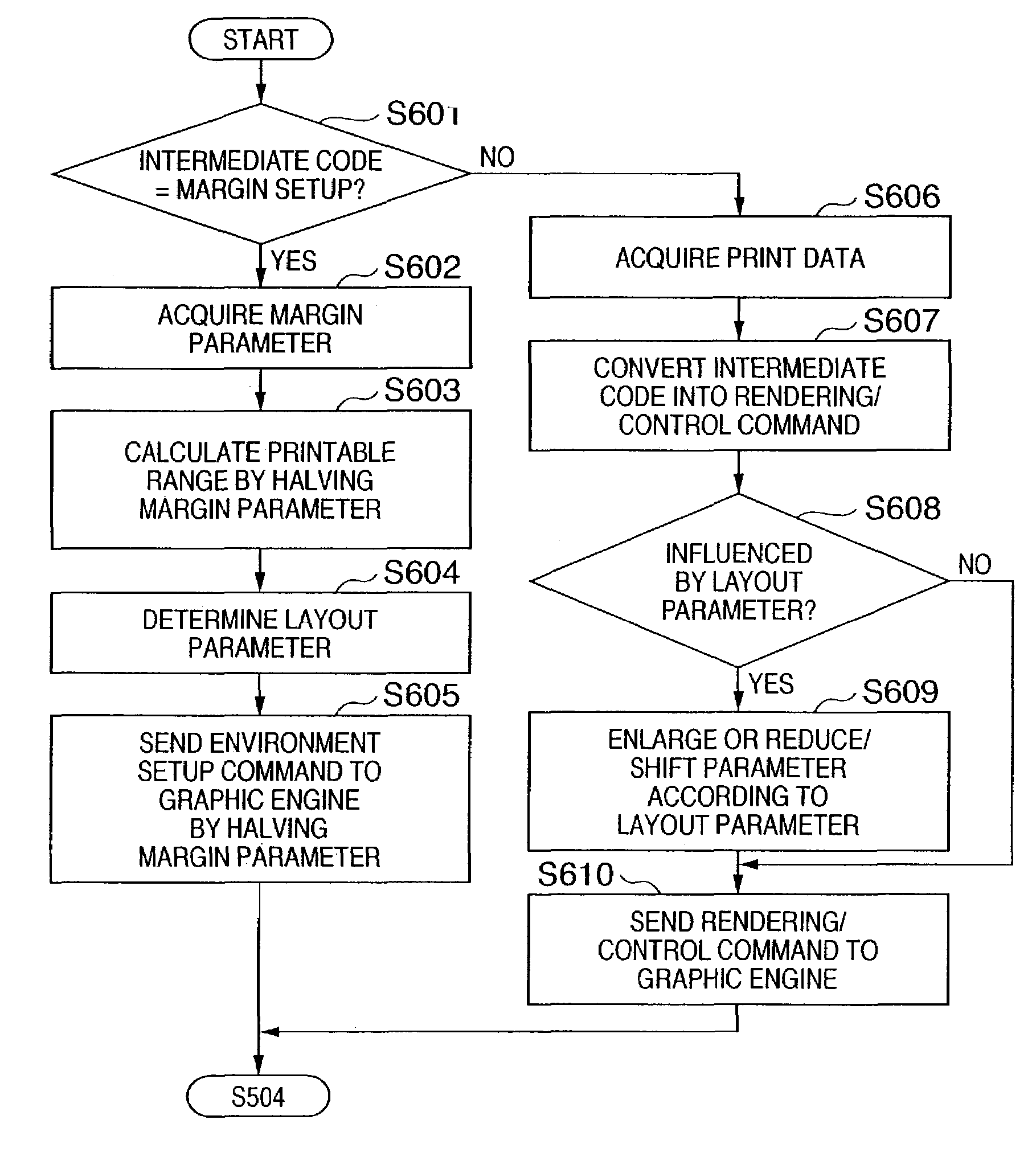
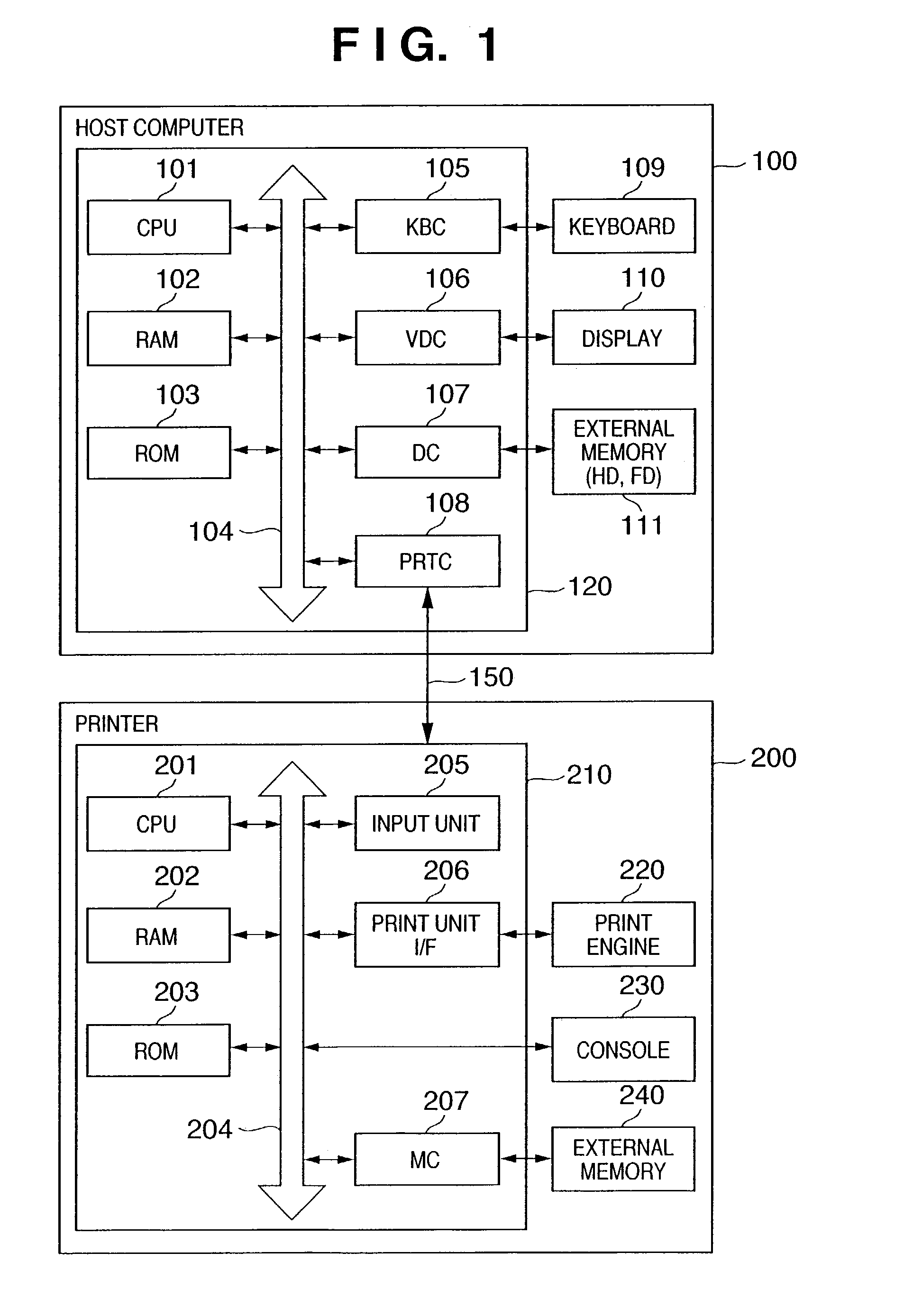
[0028]FIG. 1 is a block diagram showing an example of the arrangement of a printer control system according to an embodiment of the present invention. The present invention is not limited to the system arrangement shown in FIG. 1 as long as the functions of the present invention are implemented. For example, the present invention can be equally applied to a standalone apparatus, a system including a plurality of apparatuses, or a system which connects apparatuses via a network such as a LAN (Local Area Network), WAN (Wide Area Network), or the like to execute processes. A computer program according to the present invention can be recorded on a magnetic disk such as a FD (Flexible Disk) or the like, or an optical disk such as a CD-ROM (Compact Disk ROM) or the like, and can be supplied to the printer control system. Also, the program can be saved in a Web site of the Internet or BBS (Bulletin Board System; a message exchange system using computers), and can be supplied to the printer...

second embodiment

[0078]When a binding margin is added to a print job consisting of pages with a plurality of paper sizes and print directions, various combinations are logically available. Since these combinations are determined based on various conditions of the printer 200, and paper feed and exhaust mechanisms, a binding method that the user did not intend may be selected in some situations.

[0079]Hence, by providing a setup window which limits combinations of paper sizes and their binding methods to some extent, and displays them to the user, data can be output in a combination of user's choice.

[0080]FIG. 9 shows an example of a binding margin setup window when various paper sheets are used. As shown in FIG. 9, if combinations of paper sheets are limited (e.g., only a combination of A4 and A3 sheets), when the print directions (landscape, portrait) and binding margin positions of respective paper sheets are displayed as examples, the user selects a combination of paper sheets, print directions, a...


PUM


Abstract

This invention relates to a technique that prevents an image from falling outside a given range when a printer is controlled to form an image on an arbitrary medium while assuring a margin of a predetermined amount. A host computer shifts an image by only a partial amount of a target margin amount in a predetermined direction within an effective print range of a medium. Furthermore, the host computer controls a printer to form the image by further shifting the image by nearly the remaining amount of the target margin amount so as to form an image within the effective print range. In this way, since the host computer and printer add a margin in two steps, print data can be prevented from falling outside a given range upon processing a binding margin on the printer side.

Description

RELATED APPLICATION[0001]This application claims priority from and incorporates herein by reference the entire disclosure of Japanese Patent Application No. 2002-007986, filed Jan. 16, 2002.FIELD OF THE INVENTION[0002]This invention relates to a print layout technique and, more particularly, to a print layout technique which is suitably used in a print process while assuring a margin such as a binding margin or the like in a print system which comprises an information processing apparatus such as a personal computer or the like, and a printing apparatus such as a printer or the like.BACKGROUND OF THE INVENTION[0003]A conventional binding margin setup process (margin setup) in a print process by a printer merely shifts the print positions in the right-and-left or up-and-down direction in correspondence with the binding margin. For this reason, print data may fall outside an effective print range of a paper sheet depending on the selected binding margin. Normally, since print data whi...

Claims


Application Information

Patent Timeline
Patent Type & Authority Patents(United States)
IPC IPC(8): G06F15/00B41J21/00G06F3/12G06K15/02
CPCG06K15/02G06K15/021G06K15/181
Inventor UCHIDA, TATSURO
Owner CANON KK
Why Eureka
Try Eureka