
Biometric imaging system and method

a biometric and imaging system technology, applied in the field of fingerprint imaging system, can solve the problems of high maintenance high cost of custom-made consoles, and high labor intensity of workers, and achieve the effect of reducing labor intensity and reducing labor intensity

Inactive Publication Date: 2007-04-10
HID GLOBAL CORP
View PDF234 Cites 59 Cited by
  • Summary
  • Abstract
  • Description
  • Claims
  • Application Information

AI Technical Summary

Benefits of technology

The system simplifies the fingerprint capture process, reduces complexity and cost, ensures FBI certification compliance, and provides high-quality fingerprint images with real-time feedback and automatic hand determination, enhancing efficiency and usability.

Problems solved by technology

Unfortunately, the process of rolling each finger to obtain prints during an arrest or background check is a relatively complex and time consuming process.
Custom-made consoles are very expensive and are manufactured at low volume rates.
Custom-made consoles are also burdened with high maintenance costs.
When the console malfunctions, the entire system is inoperable.

Method used


Image

  • Biometric imaging system and method
  • Biometric imaging system and method
  • Biometric imaging system and method

Examples


Embodiment Construction

[0042]While the present invention is described herein with reference to illustrative embodiments for particular applications, it should be understood that the invention is not limited thereto. Those skilled in the art(s) with access to the teachings provided herein will recognize additional modifications, applications, and embodiments within the scope thereof and additional fields in which the present invention would be of significant utility.

Sections

[0043]Terminology

[0044]Overview

[0045]The Electrical System

[0046]The Optical System

[0047]Finger Guide and Platen

[0048]Real-Time Feedback Quality Indicators

[0049]Overall Method of Capturing and Processing Prints

[0050]Method for Determining Quality of Captured Fingerprints

[0051]Slap Image Processing

[0052]Left Hand / Right Hand Determination

[0053]Print Images

[0054]Overall System

Terminology

[0055]To more clearly delineate the present invention, an effort is made throughout the specification to adhere to the following term definitions consistent...


PUM


Abstract

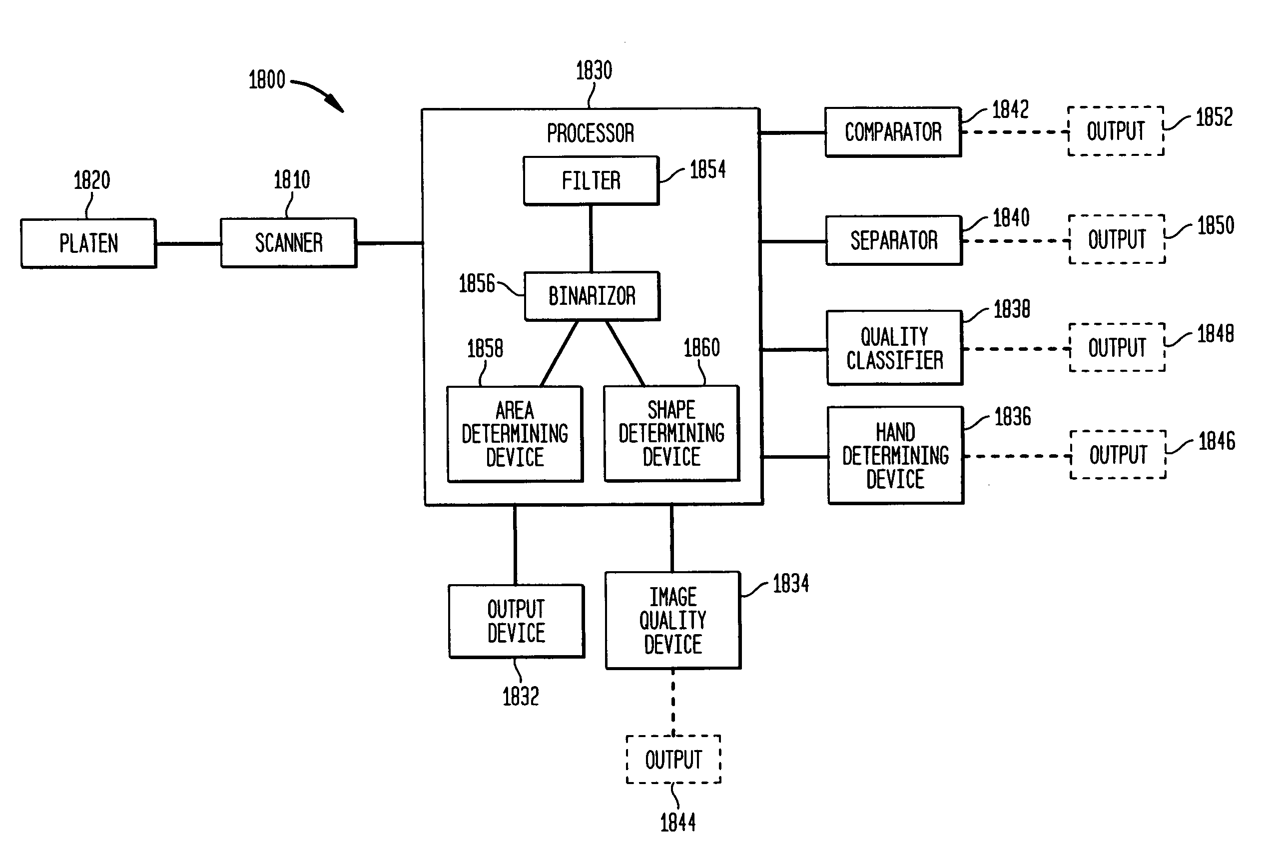
A method and system of obtaining a ten-print plain impression fingerprint includes scanning a print image, processing the scanned image, separating the processed image into individual fingerprint images, and determining how many print images have been scanned. The method also includes comparing the print image to a previously scanned print image, quality classifying the separated images, indicating a quality classification of the print image based on the classifying step, and determining whether the print image is of a good quality. The system can include a ten-print scanner having a finger guide and a platen used to position four finger slaps onto the platen.

Description

CROSS-REFERENCE TO RELATED APPLICATIONS[0001]The present application claims the benefit of U.S. Provisional Patent Application No. 60 / 348,678, filed on Jan. 17, 2002, which is incorporated by reference herein in its entirety.[0002]The present application is related to U.S. patent application Ser. No. 10 / 345,366, filed concurrently herewith, which is incorporated by reference herein in its entirety.[0003]The present application is related to U.S. patent application Ser. No. 10 / 050,046, filed Jan. 17, 2002 (now U.S. Pat. No. 6.954.260 that issued Oct. 11. 2005), and entitled “Systems and Methods For Illuminating A Platen In A Print Scanner,” and U.S. patent application Ser. No. 10 / 047,983, filed on Jan. 17, 2002 (now U.S. Pat. No. 6,809,303 that issued Oct. 26, 2004), and entitled “Platen Heaters For Biometric Image Capturing Devices,” which are both incorporated by reference herein in their entireties.BACKGROUND OF THE INVENTION[0004]1. Field of the Invention[0005]The present inventi...

Claims


Application Information

Patent Timeline
Patent Type & Authority Patents(United States)
IPC IPC(8): G06K9/00G06T7/00G06T1/00
CPCG06K9/00013G06K9/00046G06K9/00912G06K9/036G06V40/1324G06V40/67G06V10/993
Inventor MCCLURG, GEORGE WCARVER, JOHN FSCOTT, WALTER GZYZDRYN, GREGORY
Owner HID GLOBAL CORP
Learn More