Plant pot made from deep-drawn plastic

a deep-drawn, plastic technology, applied in the field of plant pots, can solve the problems of two matching ledges, presenting an undercut, and being difficult to realiz

Inactive Publication Date: 2007-04-17
POEPPELMANN HLDG GMBH & CO KG
View PDF29 Cites 42 Cited by
  • Summary
  • Abstract
  • Description
  • Claims
  • Application Information

AI Technical Summary

Benefits of technology

[0008]It is therefore an object of the present invention to configure a plant pot or other plastic container having a stackable shape such that it can be removed from the mold after deep-drawing by a production-friendly, quick removal step and, at the same time, provides a load-resistant, precisely spaced-apart stacking position during stacking, during transport as well as for removal from the stack for further use of the pot, in particular, also for automated removal from the stack.
[0011]It is important that the smooth rim contour is dissolved by the wave shape and is therefore designed to yield. In this way, at least a partial deformation and thus also removability in the case of larger undercuts and also larger contact areas of the ledges on one another can be obtained with a Z-shaped area comprised of the ledges and the intermediate support area.

Problems solved by technology

However, two matching ledges in this context, which have substantially horizontally extending surfaces that face upwardly or downwardly and overlap in a plan view, cannot be easily realized in the case of deep-drawn pots because they require a Z-shaped course of the wall where the ledges are connected to one another by means of an intermediate support area.
This intermediate support area extends conically opposite to the general conical configuration of the pot and presents an undercut when removing the pot from the deep-drawing mold.
This is possible only to a limited extent.
Accordingly, the annual support surfaces of stacked pots are limited.
The risk that the pots in the stack will deform under their own weight or when receiving external pressure and will slide into one another at least over portions of their periphery is significant.
Such pots can be manually removed from their stacks only with difficulty, and automated removal is generally not possible at all.
At the same time, the deformation in the stack creates the risk of overloading and damaging of the material as well as, for example, in the case of extended storage, the risk of permanent deformation.

Method used


Image

  • Plant pot made from deep-drawn plastic
  • Plant pot made from deep-drawn plastic
  • Plant pot made from deep-drawn plastic

Examples


Embodiment Construction

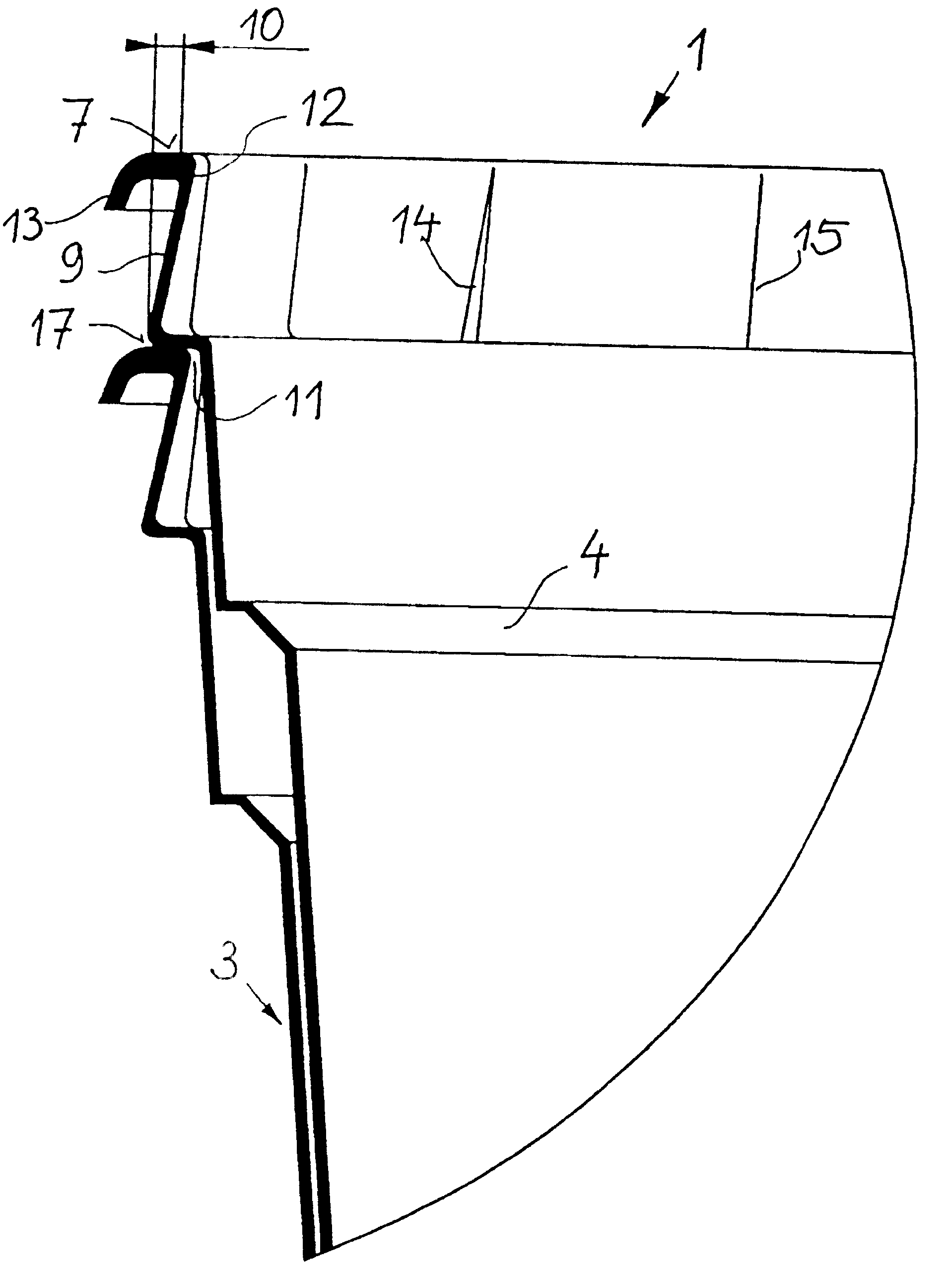
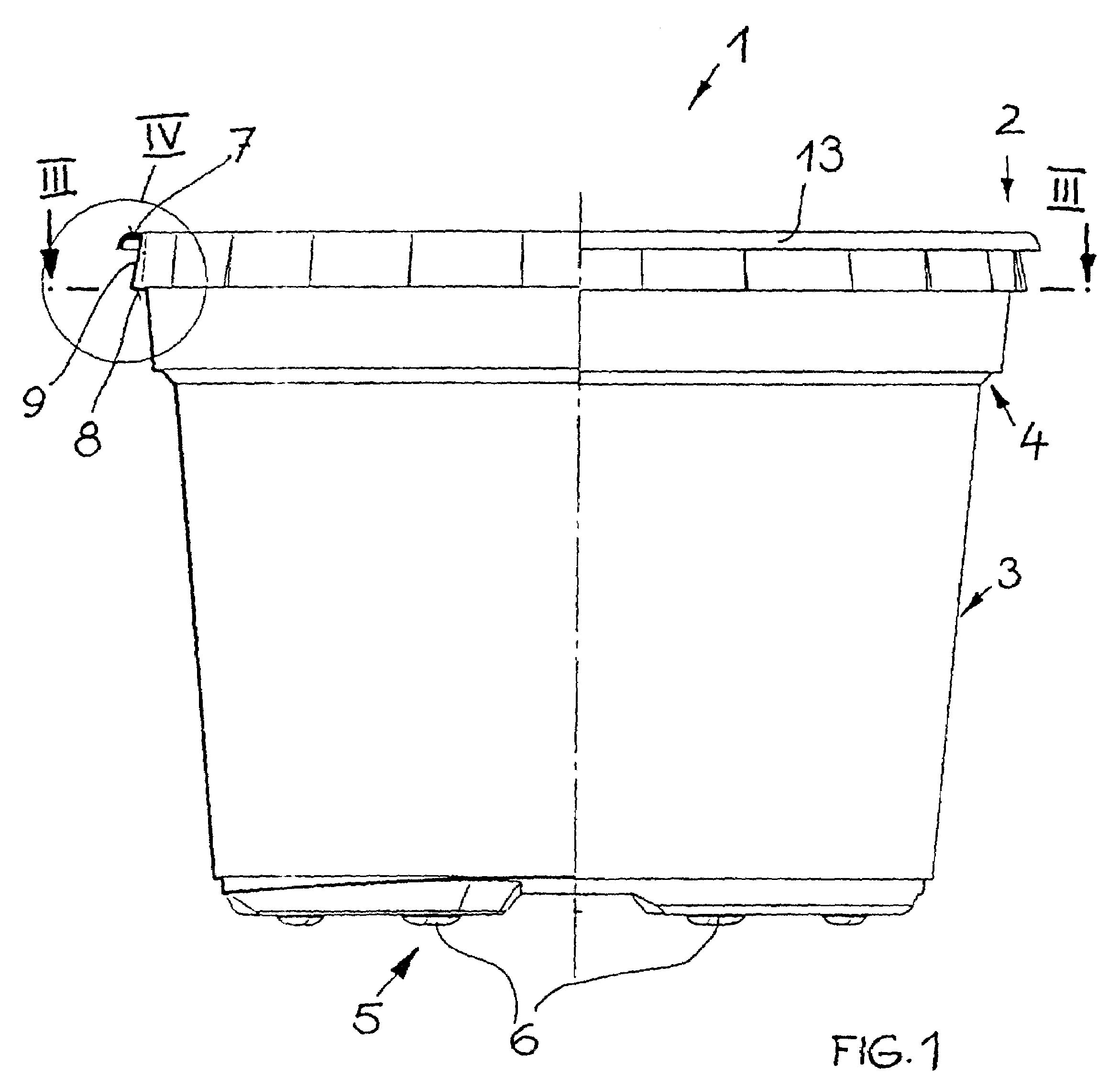
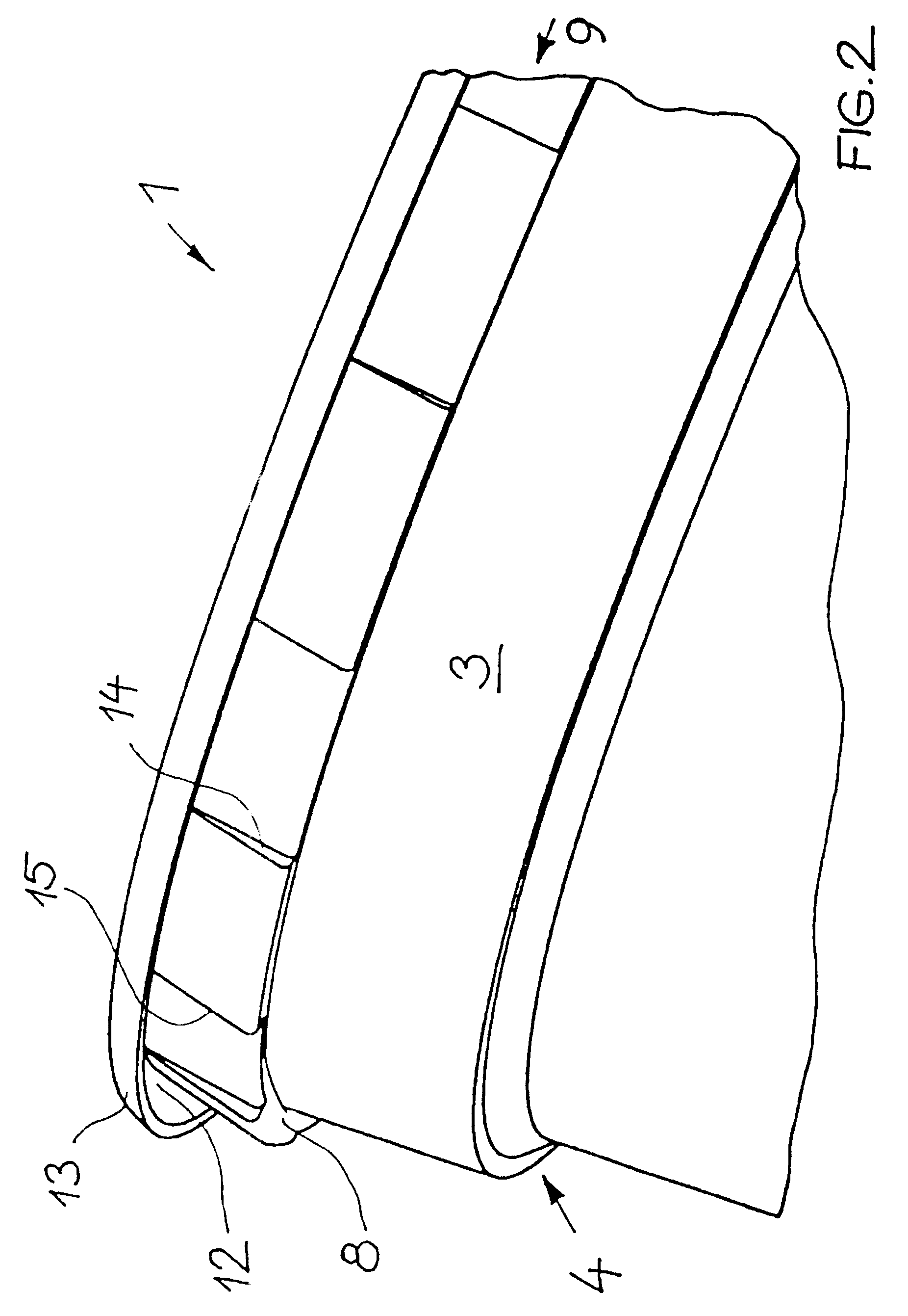
[0018]The plastic container in the form of a plant pot 1 illustrated in FIG. 1 is a deep-drawn plastic part produced from a flat sheet or film and stamped. As a result of the shaping process, it has accordingly a pot shape with a simple continuous and unbranched wall comprising a generally conical pot wall 3, a bottom 5, and, at the top, a rim area 2. The pot wall 3 has an incorporated step 4 for reinforcement purposes; for reinforcement purposes and for effecting drainage of the pot, the bottom 5 is provided with a profiling which is not illustrated in detail. The bottom 5 has cup-shaped legs 6 for spacing it from a surface onto which it is placed. Moreover, the plant pot 1 is provided in the bottom area with holes (not illustrated) for watering and drainage purposes. The plant pot 1 shaped accordingly has a generally downwardly tapering shape, which goes hand in hand with the requirements for ease of removal from the hollow mold, on whose inner side the formed pot rests, after dee...


PUM


Abstract

A stackable deep-drawn plastic container has an at least slightly conical wall and a bottom connected to the conical wall. The wall has a rim area remote from the bottom. The rim area has a first ledge and a second ledge located below the first ledge. It also has an intermediate support area having a first end connected to the first ledge and a second end connected to the second ledge. A stacking spacing of the deep-drawn plastic container when stacked in a stack is determined by the first and second ledges. The first and second ledges in a plan view onto the rim area overlap at least partially. The intermediate support area has a first width at the first ledge that is smaller than a width at the second ledge. The intermediate support area has a wave shape at least at one of the first and second ends.

Description

CROSS REFERENCE TO RELATED APPLICATIONS[0001]This is a continuation of International Application PCT / EP02 / 09566 with an international filing date of Aug. 28, 2002, not published in English under PCT Article 21(2), and now abandoned.BACKGROUND OF INVENTION[0002]1. Field of the Invention[0003]The invention relates to a plant pot or a similar plastic container of deep-drawn plastic material having a stackable basic shape that is at least somewhat conical, wherein the stacking spacing is determined by two ledges which, in a plan view, at least partially overlap one another and which are connected to one another by an intermediate support area. In contrast to the shape needed for stackability, the intermediate support area has a width at the upper ledge that is smaller than a width at the lower ledge.[0004]2. Description of the Related Art[0005]In the case of stacking pots or containers, usually a coaxial stacking arrangement with a precisely defined stacking spacing or distance is deman...

Claims


Application Information

Patent Timeline
Patent Type & Authority Patents(United States)
IPC IPC(8): A01G9/02B65D1/42B65D21/00
CPCA01G9/021
Inventor SIEVERDING, ALFONS
Owner POEPPELMANN HLDG GMBH & CO KG
Why Eureka
Try Eureka