
Magnetic actuator using ferrofluid slug

a technology of ferrofluid slugs and magnets, which is applied in the direction of positive displacement liquid engines, magnetic bodies, laboratory glasswares, etc., can solve the problems of inconvenient use, difficult cleaning, and high cost of non-contact devices for dispensing droplet sizes in the intermediate range, and achieve precise droplet sizes and increase the throw of the actuator

Active Publication Date: 2007-04-17
XEROX CORP
View PDF25 Cites 24 Cited by
  • Summary
  • Abstract
  • Description
  • Claims
  • Application Information

AI Technical Summary

Benefits of technology

[0011]Accordingly, various implementations provide an actuator device that is compatible with fluidic systems. Further, various implementations provide systems and methods which are capable of dispensing intermediate sized droplets, particularly, intermediate sized droplets of biological fluids. Also, various implementations provide a droplet dispensing device that is inexpensive and disposable and / or easily cleaned.
[0012]A magnetostatic actuator can be used to displace a volume of fluid. For example, a droplet dispenser system may dispense intermediate sized droplets. Such a system may be relatively inexpensive to implement, and also may be disposable.
[0014]A set of current pulses may be delivered to a plurality of electrical coils surrounding the tube. By using a particular profile of current pulses, the ferrofluid slug may be driven in a particular trajectory within the tube, to provide, for example, a “whiplash” profile which can dispense more precise droplet sizes than otherwise would be possible. The plurality of current pulses may also be applied to the plurality of coils to increase the throw of the actuator.

Problems solved by technology

Such devices for non-contact dispensing of droplet sizes in the intermediate range tend to be expensive, difficult to clean, and not disposable.
When working with sticky fluids such as biological samples and proteins, the devices may become clogged, requiring extensive cleaning and vacuum drying in order to begin operating reliably and reproducibly again.

Method used


Image

  • Magnetic actuator using ferrofluid slug
  • Magnetic actuator using ferrofluid slug
  • Magnetic actuator using ferrofluid slug

Examples


Embodiment Construction

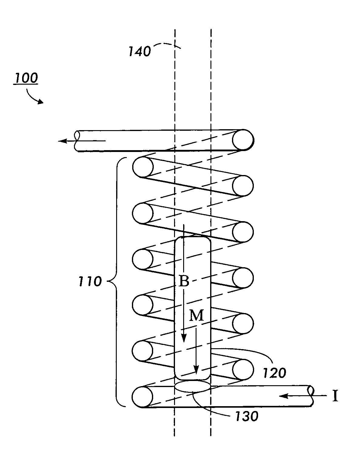
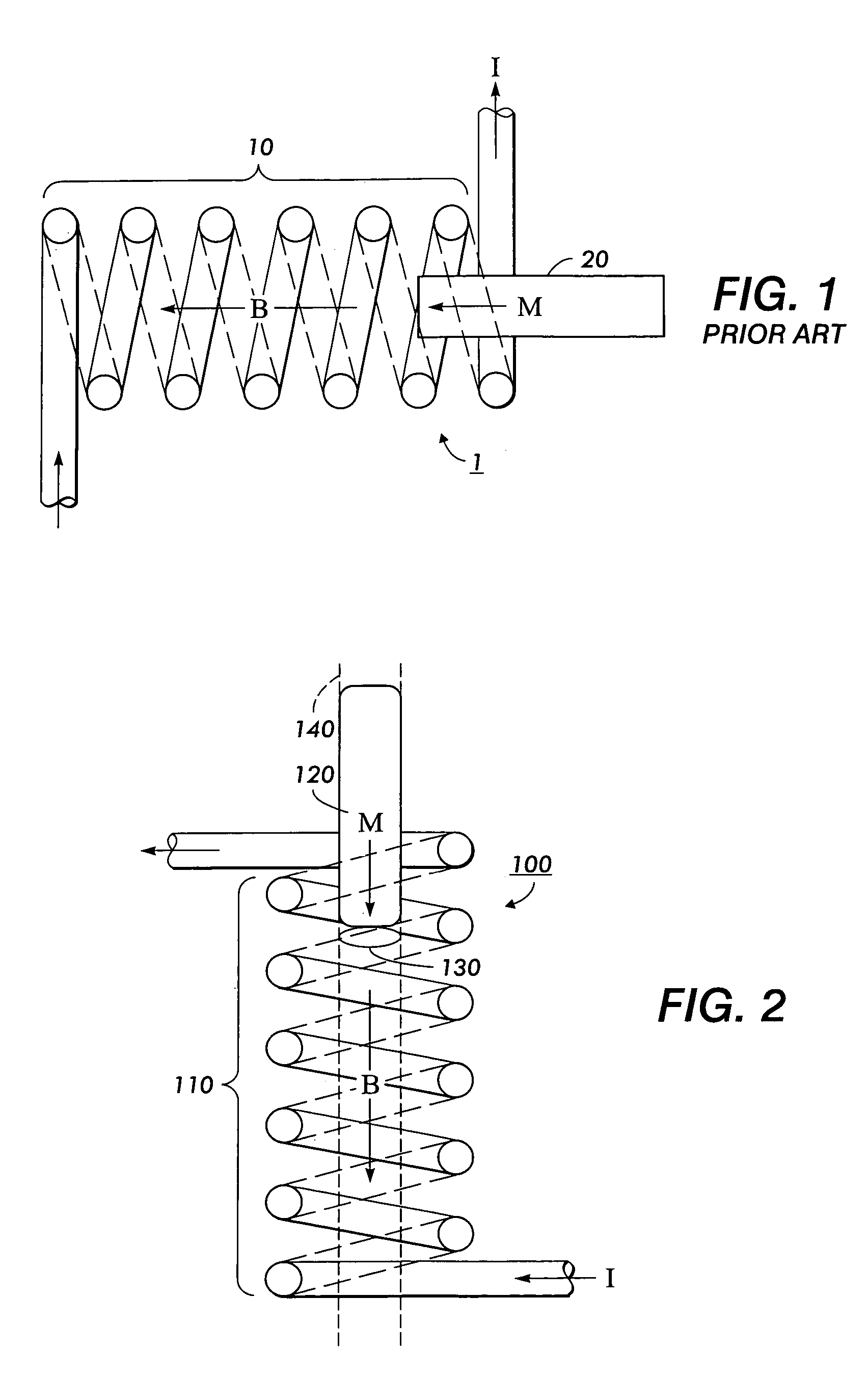
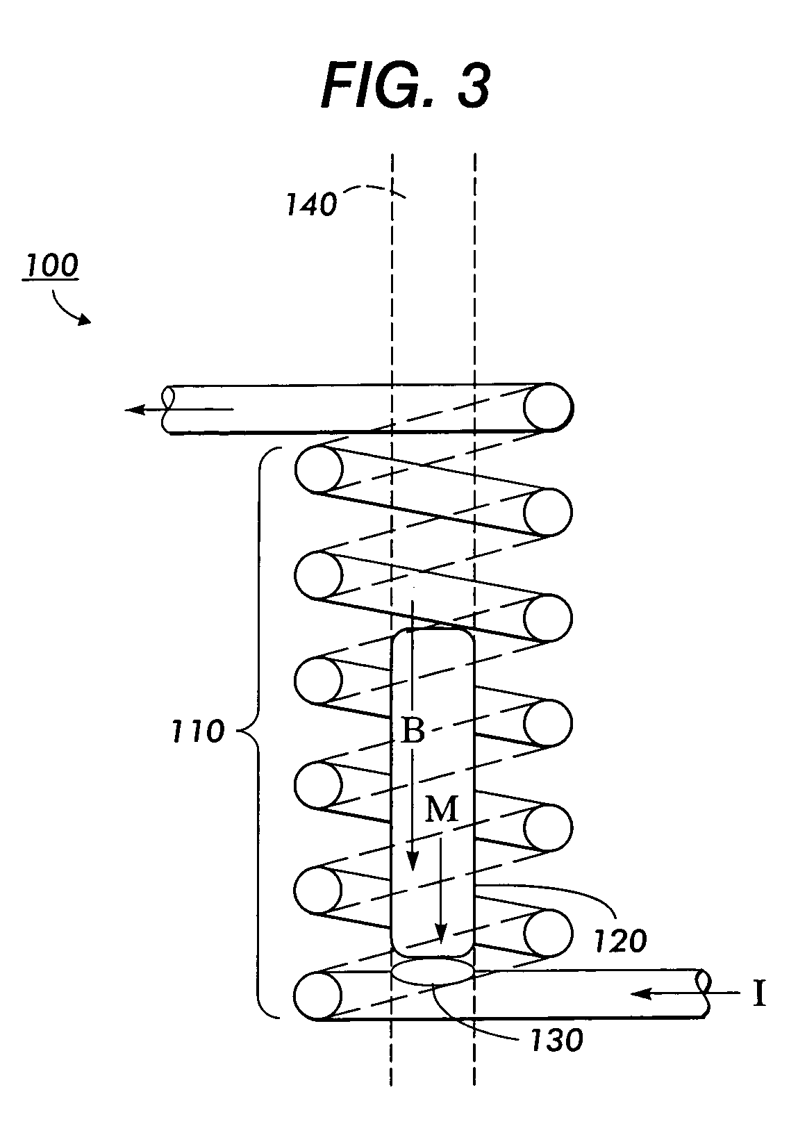
[0032]Systems and methods are disclosed which provide a ferrofluid magnetostatic actuator including a coil of conductive wire wrapped around a tube containing a ferrofluid slug. In various implementations, the tube is cylindrical and the coil is energized by a current which generates a magnetic field along the axis of the coil. The ferrofluid slug interacts with the magnetic field, and the interaction draws the ferrofluid slug toward the interior of the coil. The displacement of the ferrofluid slug may be used to actuate any of a number of other devices, such as switches or valves.

[0033]The word “slug” as used herein is used according to the Merriam-Webster Online Dictionary definition (http: / / www.m-w.com / cgi-bin / dictionary?book=Dictionary&va=slug) of “a detached mass of fluid (as water vapor or oil) that causes impact (as in a circulating system).”

[0034]FIG. 2 shows an exemplary ferrofluid magnetostatic actuator 100. The ferrofluid magnetostatic actuator includes a coil 110 which i...


PUM


Abstract

A magnetostatic actuator uses a ferrofluid slug confined in a cylindrical tube which is wrapped in a conducting coil. By applying a current to the coil, a magnetic field is generated inside the coil. The ferrofluid slug may be attracted to the interior of the coil by the interaction of its magnetic moment with the field generated inside the coil. Movement of the ferrofluid slug in response to the magnetic field may be used to actuate various devices, such as a droplet dispenser.

Description

BACKGROUND OF THE INVENTION[0001]1. Field of Invention[0002]This invention is directed to magnetic actuators.[0003]2. Description of Related Art[0004]Actuators are, in general, magnetostatic, electrostatic, or mechanical. Magnetostatic actuators include well known solenoids, in which a coil of wire is energized to create a magnetic field in the interior of the coil which then interacts with a magnetic solid core, to attract the magnetic core into, or repel the magnetic core from, the interior of the coil.[0005]FIG. 1 illustrates an example of a known solenoid actuator 1. A coil of wire 10 is energized by a current I, which produces a magnetic field B within the interior of coil 10. Magnetic core 20 interacts with magnetic field B created within coil 10 such that magnetic core 20 is pulled toward the interior of the coil. As core 20 is drawn into the interior of coil 10, the displacement may be used to actuate other devices such as valves or switches, which may be coupled to magnetic...

Claims


Application Information

Patent Timeline
Patent Type & Authority Patents(United States)
IPC IPC(8): B41J2/04B41J2/035B65D47/18F15C1/04B01L3/02
CPCB01L3/0268B05B17/04H01F7/1607B01L2300/0838B01L2400/043Y10S137/909Y10T137/2191Y10T137/2213
Inventor PEETERS, ERIC
Owner XEROX CORP
Learn More