Deviation ring for a self-distributing centrifuge

a technology of discs and centrifuges, which is applied in the direction of centrifuges, rotary centrifuges, etc., can solve the problems of inability to collect solids centrally, and achieve the effect of minimising possible product losses

Inactive Publication Date: 2007-04-17
WESTFALIA SEPARATOR AG
View PDF27 Cites 22 Cited by
  • Summary
  • Abstract
  • Description
  • Claims
  • Application Information

AI Technical Summary

Benefits of technology

[0011]The invention relates to a device comprising a paste deflector ring and a paste container which is connected to it or can be released and is able to receive the paste from a plurality of drum emptying operations. This ring is designed in such a way that deflection entails the minimum possible product losses.

Problems solved by technology

This has the drawback that the solids which are centrifuged out can remain stuck in the region of the centrifuging zone, making central collection of the solids impossible.

Method used


Image

  • Deviation ring for a self-distributing centrifuge
  • Deviation ring for a self-distributing centrifuge
  • Deviation ring for a self-distributing centrifuge

Examples


examples

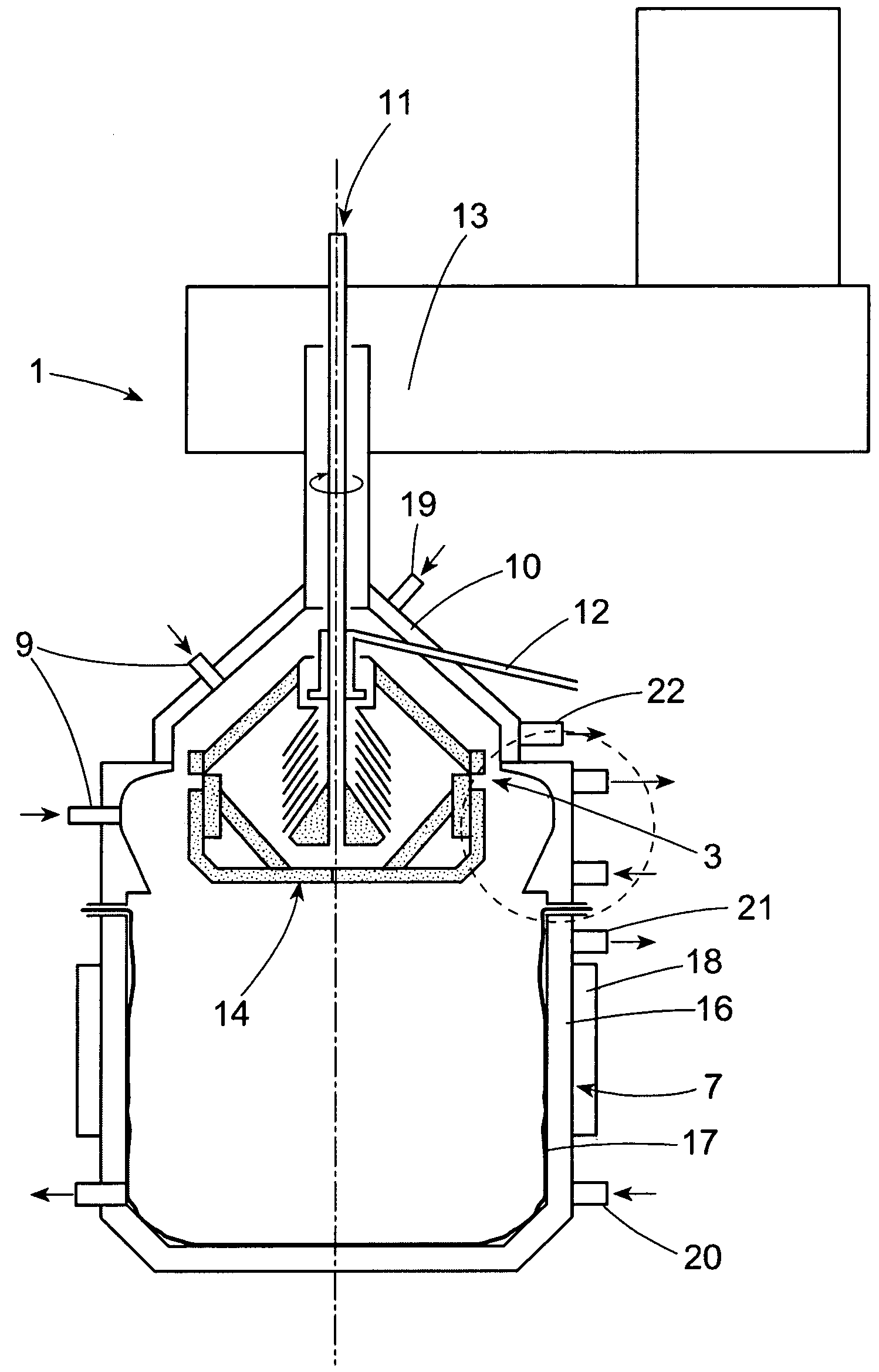
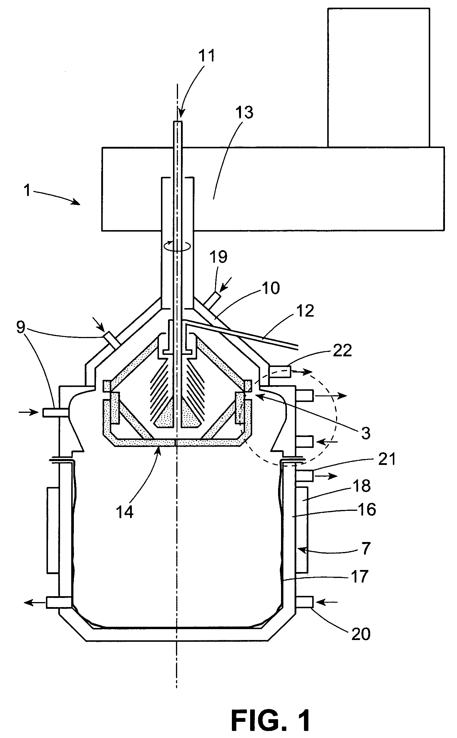
[0048]The discharge of a biological paste which is formed during the fractionation of human blood plasma takes place from a centrifuge drum 14 having an external diameter of 468 mm at a drum rotational speed of 7000 rpm, with the blood plasma paste being deflected by a paste deflector ring 4. The centrifuge 1 has a drive part 13 for driving the drum 14, with a feed line 11 for the plasma. The drum 14 is suspended in a dividable lower part of the centrifuge 1 which comprises the jacket housing 10, with feed lines 19 and discharge lines 22 for a cooling liquid and lines 9 for introducing liquid nitrogen, the deflector ring 4 and the collection vessel 7, with flexible collection bag 17 inserted therein. The collection vessel has a cooling jacket 16 with feed lines 20 and discharge lines 21 and also welded-on transport brackets 18. The drum 14 also has an outlet 12 for the clarified liquid. FIG. 2 shows the deflector ring 4 in detail. The impact wall 2 of the paste deflector ring 4 is a...


PUM


Abstract

The invention relates to a deviation ring for paste comprising an annular rebound wall (2) for a self-distributing centrifuge (1). The invention also relates to a corresponding self-distributing centrifuge (1). In the deviation ring, the angle of incidence ? of the tangents of the rebound wall (2) of the deviation ring (4), opposite the distribution slit (3) of the centrifuge (1), in relation to the horizontal, is between 3 and 60° over the entire opening width of the distribution slit (3).

Description

[0001]This is a 371 of PCT / EP02 / 07563 filed 8 Jul. 2002 (international filing date).[0002]The invention relates to equipment for separating liquids and solids in centrifuges, in particular disk separators with automatic discharge. The invention relates in particular to a paste deflector ring with an annular impact wall for a self-discharging centrifuge and to the self-discharging centrifuge itself.BACKGROUND OF THE INVENTION[0003]Disk separators are centrifuges equipped with a central inlet for the suspension, conical disks which are located in the drum and which act as separators for fine particles as a result of the centrifugal force which is present and the short sedimentation paths. The particles which have been separated out slide along the disks into the solids collection space toward the maximum diameter of the drum. The clarified liquid is discharged over an overflow weir without pressure or under pressure by means of what is known as a gripper designed as a pump impeller.[0...

Claims


Application Information

Patent Timeline
Patent Type & Authority Patents(United States)
IPC IPC(8): B04B7/04B04B15/02B04B1/12B04B1/10B04B9/12B04B11/00B04B11/04B04B11/05
CPCB04B1/10B04B7/04B04B9/12B04B11/04B04B11/05
Inventor HIMMEN, ERNST-ULRICHLONGERICH, MARKUSSCHOLZ, JURGENFREYER, DETLEFESSER, ULRICH
Owner WESTFALIA SEPARATOR AG
Why Eureka
Try Eureka