Apparatus for administering a gas to a person or an animal

a technology for administering gas and apparatus, which is applied in the direction of respirator, valve details, life-saving devices, etc., can solve problems such as inability, and achieve the effect of building up gas pressure in the breathing tub

a technology for administering gas and apparatus, which is applied in the direction of respirator, valve details, life-saving devices, etc., can solve problems such as inability, and achieve the effect of building up gas pressure in the breathing tub

US7207332B1Inactive Publication Date: 2007-04-24LUGTIGHEID GERARDUS WILHELMUS

Image

  • Apparatus for administering a gas to a person or an animal
  • Apparatus for administering a gas to a person or an animal
  • Apparatus for administering a gas to a person or an animal

Examples


Embodiment Construction

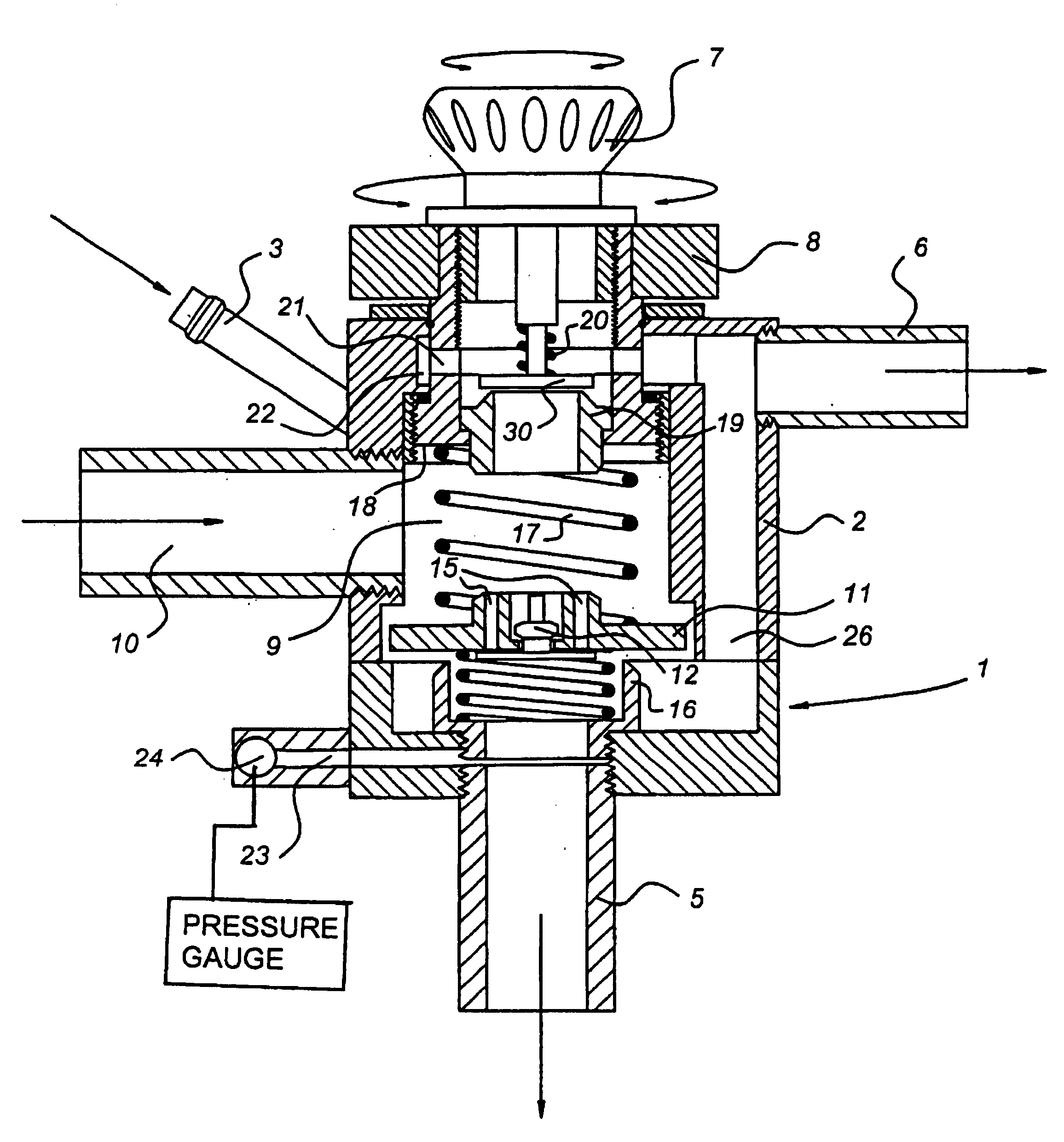
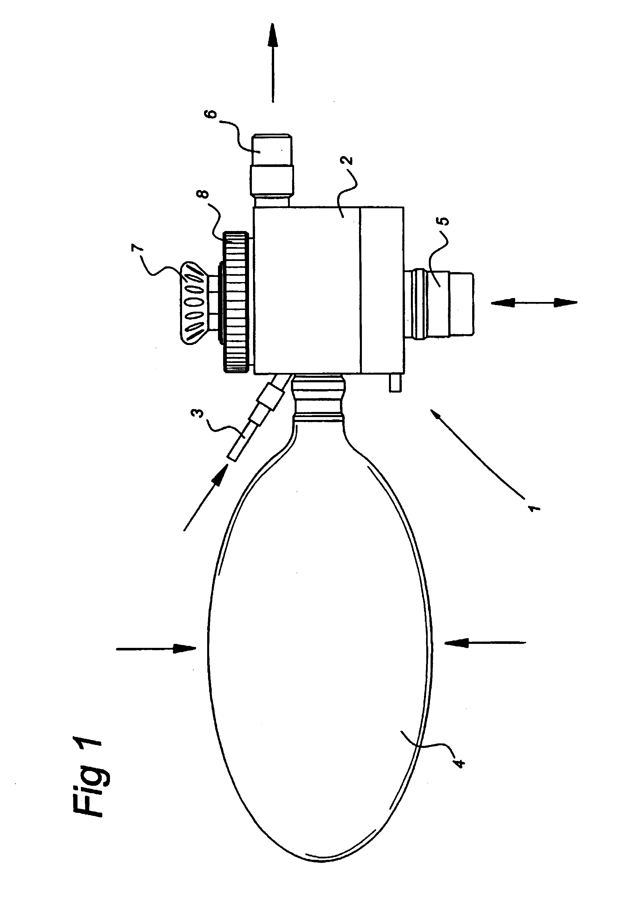
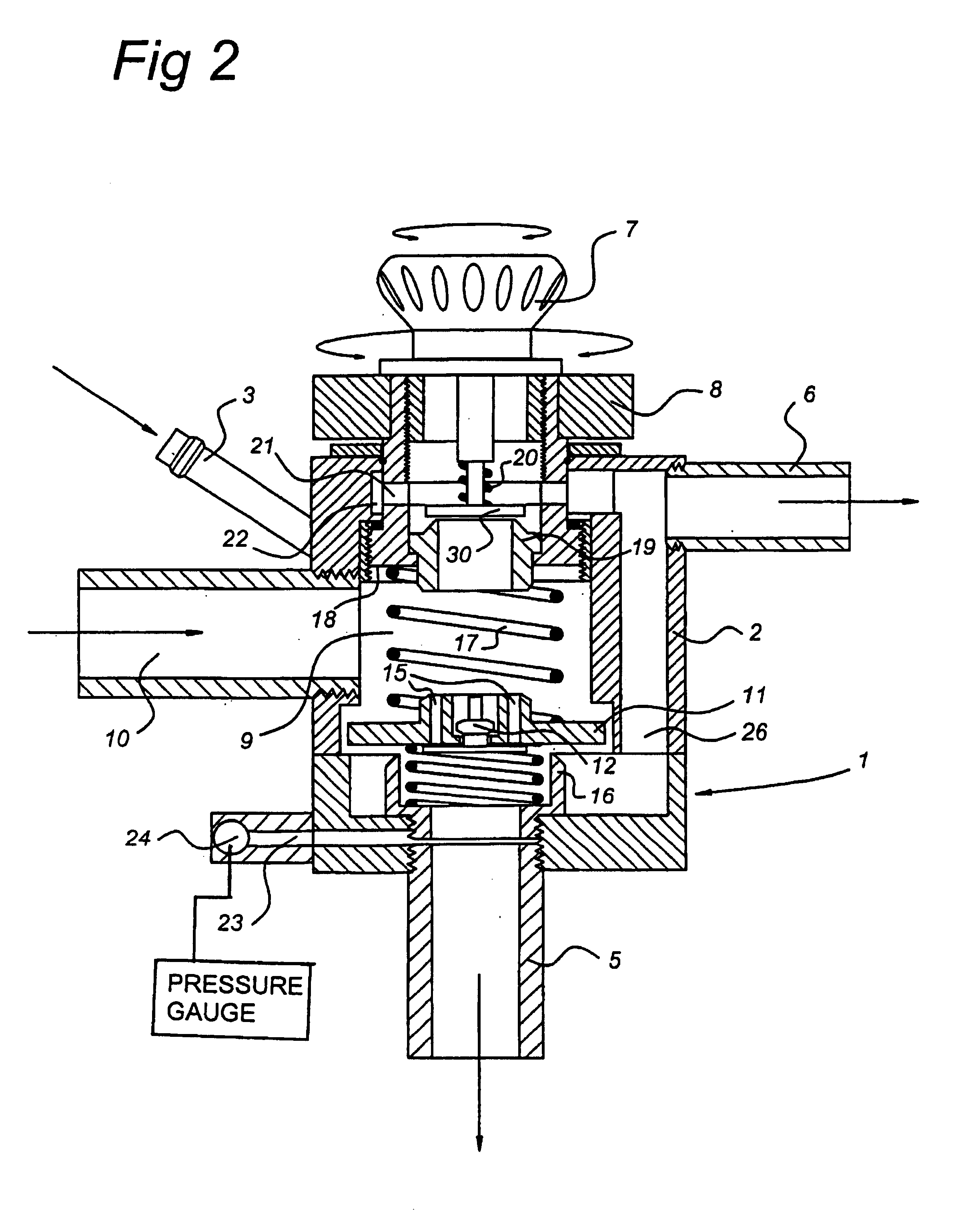
[0024]The apparatus 1 according to the invention is shown in FIG. 1. The apparatus 1 comprises a housing 2 in which a chamber for receiving gas is delimited (see FIG. 2). The housing 2 is provided with a gas line 3, which can be connected to a source (not shown) for supplying gas to the housing 2. The apparatus 1 further comprises a balloon 4. This balloon 4 can be compressed by hand (in the direction of the arrows shown in the figure) to pressurise gas that has been received in the housing 2. Gas can be discharged from the housing 2 via the breathing tube 5. In use, this breathing tube 5 is fed to a patient who has to be ventilated with the aid of the apparatus 1. When a patient exhales gas this gas is fed back to the housing 2 via the breathing tube 5. As a result of the presence of discharge channels (explained with reference to FIG. 2 et seq.), exhaled gas is fed via a discharge channel 26 to a discharge 6, which discharges said exhaled gas from the apparatus 1.

[0025]Furthermore...


PUM


Abstract

An apparatus (1) for administering a gas to a person or an animal, is provided with a chamber (9) for receiving a quantity of gas to be administered. The chamber is provided with a gas line (3) for supplying gas from a source to the chamber (9) and elements for pressurizing the gas in the chamber. The chamber (9) is connected to a breathing tube (5) for supplying pressurized gas from the chamber (9) to the person or the animal, wherein the breathing tube (5) connects to a discharge channel (26), for discharging gas exhaled by the person or the animal, via a valve (11), which restricts the flow of exhaled gas from the breathing tube (5) to the discharge channel (26) in order to build up gas pressure in the breathing tube (5) during exhalation.

Description

BACKGROUND OF THE INVENTION[0001]1. Field of the Invention[0002]The present invention relates to an apparatus for administering a gas to a person or an animal, provided with a chamber for receiving a quantity of gas to be administered, which chamber is provided with a gas line for supplying gas from a source to the chamber and means for pressurising the gas in the chamber, the chamber connecting to a breathing tube for supplying pressurised gas from the chamber to the person or the animal.[0003]2. Description of the Related Art[0004]Ventilators of the type specified in the preamble are known in the prior art. Such ventilators are used for ventilating patients. A certain quantity of gas is received in a chamber, after which the gas is brought under elevated pressure. As a result of raising the pressure, a flow channel is opened from the chamber to the breathing tube which is connected to the apparatus. The gas is administered to the patient via this breathing tube. The gas pressure i...

Claims


Application Information

Patent Timeline
24 Apr 2007
Publication
US7207332B1
IPC
A61M16/00; A61M16/08; A61M16/12; A61M16/20
CPC
A61M16/208; A61M16/0833; A61M16/0084; A61M16/0858; A61M16/209; A61M16/0078; A61M16/0816; A61M16/12
Inventors
LUGTIGHEID, GERARDUS WILHELMUS