Multi-pole transmitter source

a multi-pole transmitter and transmitter technology, applied in the field of sonic or acoustic logging of formations, can solve the problems of slow wave propagation velocity, inability to measure the shear wave velocity of a formation using a monopole transmitter, and inaccuracy of estimation, so as to achieve the effect of enhancing output pressur

Inactive Publication Date: 2007-04-24
SCHLUMBERGER TECH CORP
View PDF34 Cites 31 Cited by
  • Summary
  • Abstract
  • Description
  • Claims
  • Application Information

AI Technical Summary

Benefits of technology

[0006]The present invention addresses the above-described deficiencies and others. Specifically, the present invention provides an apparatus for generating acoustic waves in a formation traversed by a wellbore including a multi-pole transmitter, the multi-pole transmitter comprising four monopole acoustic transmitter elements housed in a drill collar, the four monopole acoustic transmitter elements being spaced around a circumference of the drill collar at approximately equal intervals. The four multi-pole acoustic transmitter elements may be operated to create a monopole, dipole, or quadrupole pressure field. According to some embodiments, each of the four monopole transmitter elements includes a cylindrical transducer and a canister surrounding the transducer, with the canister and the cylindrical transducer filled with a fluid. The canister may be made of RADEL®-R (polyphenylsulfone) and have a thickness of approximately 1 mm. The cylindrical transducer may be a PZT piezo-ceramic transducer, which is used according to some embodiments as a tube resonator as well. A voltage is preferably supplied to the PZT piezo-ceramic transducer at a frequency lower than a resonant frequency of the piezo-ceramic transducer, and at a resonant frequency of the fluid in the piezo-ceramic transducer.

Problems solved by technology

This estimate, however, is subject to inaccuracies due to tool tilt, borehole washouts, bed boundary effects, etc.
However, the more porous a formation is, the slower the wave propagation velocity is.
However, shear wave velocity of a formation cannot be measured using a monopole transmitter when the shear wave velocity is slower than the velocity of the fluid (typically drilling mud) in the wellbore.
In addition, LWD environments impose several harsh conditions and restrictions that an acoustic source transmitter must survive.
The conditions and restrictions include, among other things, very limited space for a transmitter in the drill string, a need for high output pressure signals because of the noise generated by the drill, a highly erosive, high temperature and high pressure environment, and a limited power supply.

Method used


Image

  • Multi-pole transmitter source
  • Multi-pole transmitter source
  • Multi-pole transmitter source

Examples


Embodiment Construction

[0021]Illustrative embodiments and aspects of the invention are described below. In the interest of clarity, not all features of an actual implementation are described in this specification. It will of course be appreciated that in the development of any such actual embodiment, numerous implementation-specific decisions must be made to achieve the developers' specific goals, such as compliance with system-related and business-related constraints, that will vary from one implementation to another. Moreover, it will be appreciated that such a development effort might be complex and time-consuming, but would nevertheless be a routine undertaking for those of ordinary skill in the art having the benefit of this disclosure.

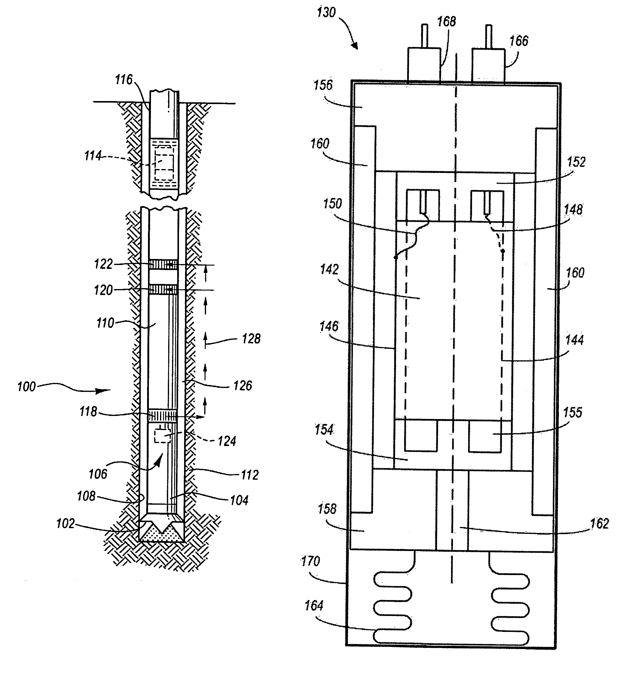
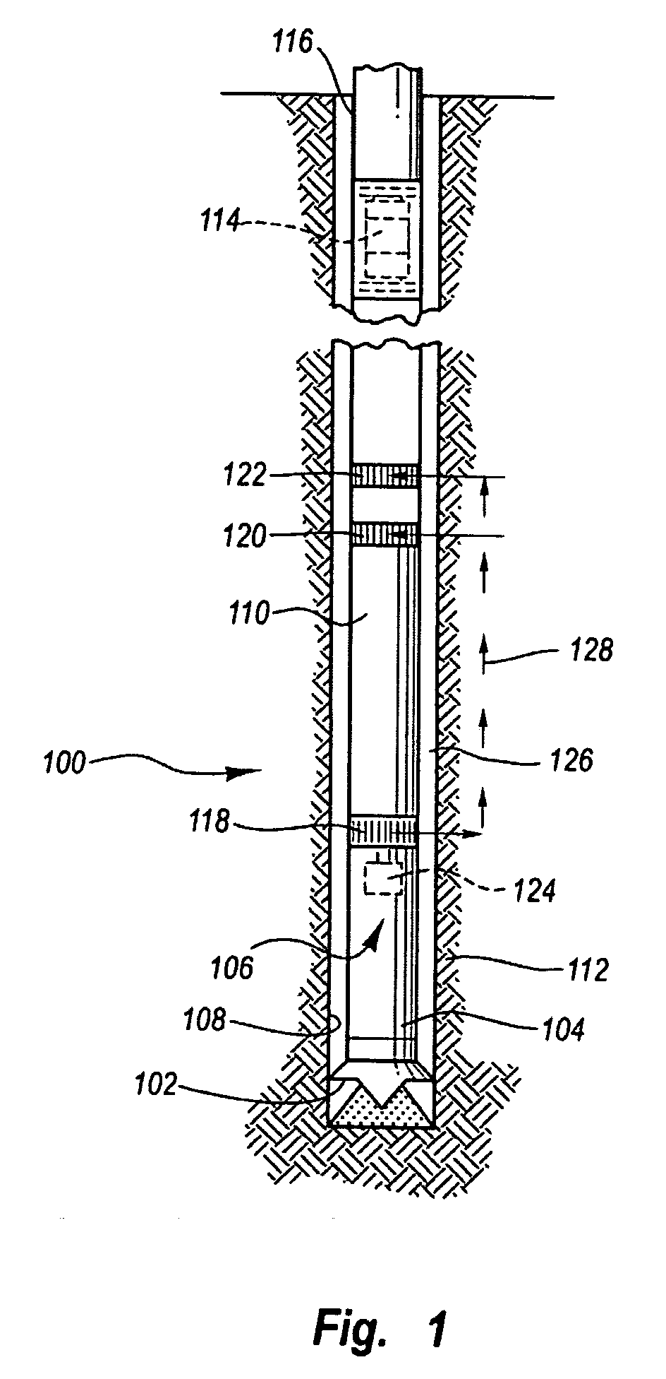
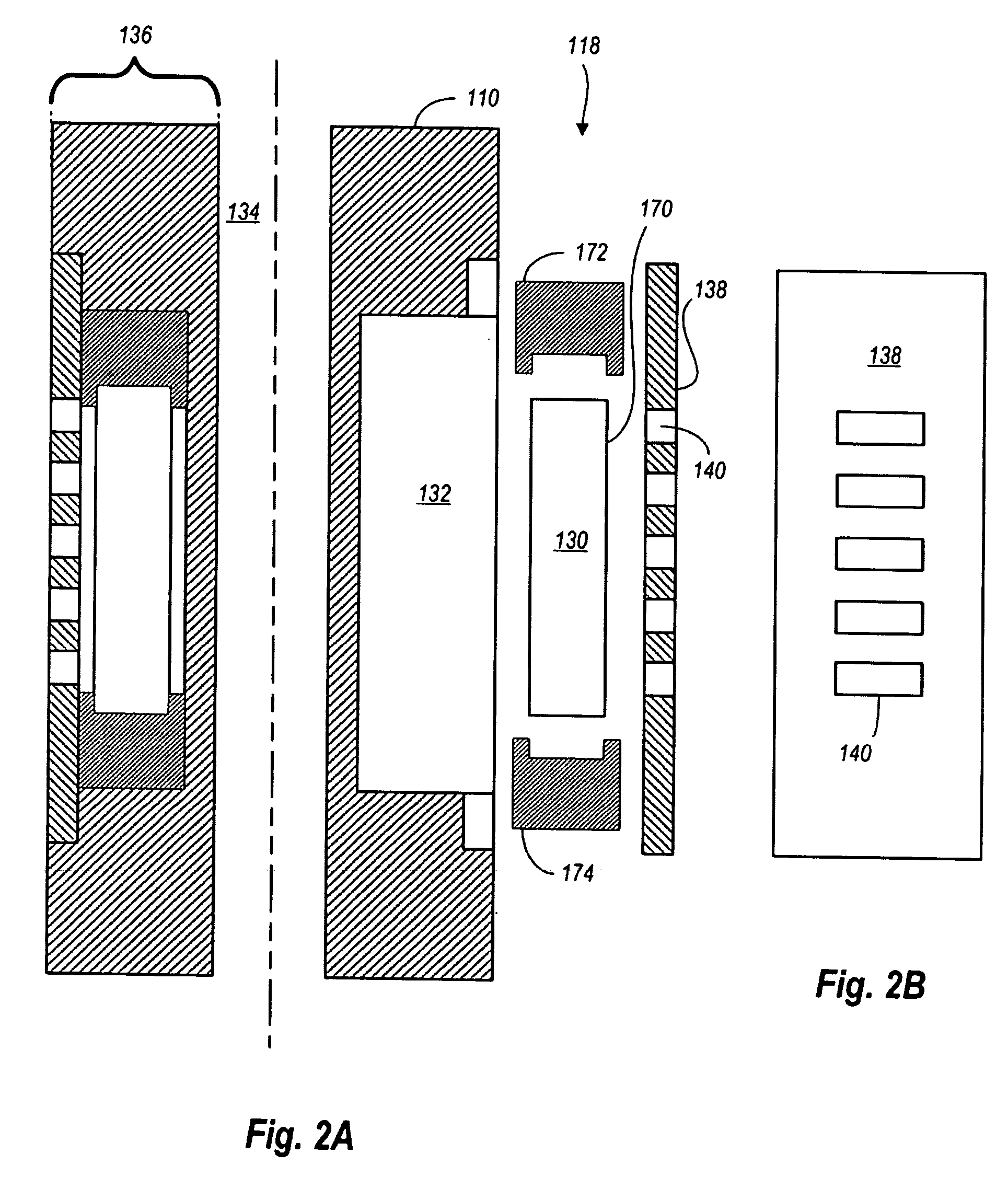
[0022]The present invention contemplates methods and apparatus for logging-while-drilling (LWD). As discussed above, previous LWD systems employ monopole transmitters to generate acoustic waves and measure formation velocity or slowness. However, monopole acoustic sour...


PUM


Abstract

Methods and apparatus facilitating logging-while-drilling (LWD) using a multi-pole acoustic transmitter source. The multi-pole transmitter source enables measurement of formation velocities, including shear wave velocities through formations that are slower than velocities through local fluids. The methods and apparatus may be utilized for LWD and wireline seismic surveys in which both the seismic or acoustic source and receivers are both deployed in a borehole, but may also be used for VSPs (vertical seismic profiling).

Description

FIELD OF THE INVENTION[0001]The present invention relates generally to sonic or acoustic logging of formations surrounding a borehole. More particularly, the present invention relates to a multi-pole transmitter source for use with a logging-while-drilling (LWD) system.BACKGROUND OF THE INVENTION[0002]The generation and recording of acoustic waves through a subterranean formation is a key measurement employed in wellbore logging. Acoustic waves propagate underground at velocities that vary from different geological formations. For example, an acoustic waves travel at about 4000 meters per second through sandstone, and about 5000 meters per second through limestone. Sound waves are generally classified into two types: longitudinal and transverse. A longitudinal or compressional wave is one in which the medium oscillates in the same direction the wave propagates. A transverse or shear wave is one in which the medium oscillates perpendicular to the direction the wave propagates. The sp...

Claims


Application Information

Patent Timeline
Patent Type & Authority Patents(United States)
IPC IPC(8): E21B47/00G01V1/44G01V1/52
CPCG01V1/52
Inventor MIYAMOTO, KENICHIROSAITO, ATSUSHI
Owner SCHLUMBERGER TECH CORP
Why Eureka
Try Eureka