Electrical connector

a technology of electrical connectors and connectors, applied in the direction of coupling contact members, fixed connections, coupling device connections, etc., can solve the problems of increased cost, one or more pin heads may not make good contact with the pcb, and the chance of uneven spacing between the carrier and the pcb is increased, so as to achieve easy and quick assembly, the carrier is easy to break, and the hole is easily pushed through. , the effect of reducing the chance of slipping

Active Publication Date: 2007-04-24
7195087 CANADA INC
View PDF5 Cites 5 Cited by
  • Summary
  • Abstract
  • Description
  • Claims
  • Application Information

AI Technical Summary

Benefits of technology

[0007]It is the purpose of the present invention to provide a connector with ‘floating’ pins that can be more easily and readily assembled with minimum breakage of the carrier. It has been discovered that the cylindrical pins, with the retaining means thereon, can be more easily pushed through the holes in the carrier if the holes are square in cross-section instead of circular while reducing cracking or breaking of the carrier. The retaining means on the pin are in the form of a collar having a leading conical portion. The conical portion deforms the square hole to a shape more closely approximating the circular plan shape of the conical portion as it passes through. The hole returns substantially to its original square shape after the retaining mean has passed through.
[0008]To make the passage of the retaining means on-the pin through the hole easier, at least part of the leading section of the pin, in front of the retaining means, can be slightly larger in diameter than the width of the hole. As the leading pin section is pushed through the hole, the part that is slightly larger in diameter produces a slight initial deformation of the hole with final deformation of the hole being formed by the passage of the collar. This two-stage deformation process, during mounting of the pins, makes it easier to push the retaining means through the hole further minimizing breakage of the carrier.
[0009]To make the passage of the retaining means even easier, it is preferred that the carrier is made from resilient material having an elongation of about 5% so that it more easily deforms without breaking.

Problems solved by technology

However, with long carriers, there is more chance of uneven spacing between the carrier and the PCB and, with uneven spacing, one or more of the heads on the pins may not make good contact with the PCB.
However, since the collar is larger than the hole, and the carriers are usually made from relatively rigid material to properly locate the pins for soldering, the carrier often cracks during mounting of the pins and must be replaced resulting in waste and added cost.

Method used


Image

  • Electrical connector
  • Electrical connector
  • Electrical connector

Examples


Embodiment Construction

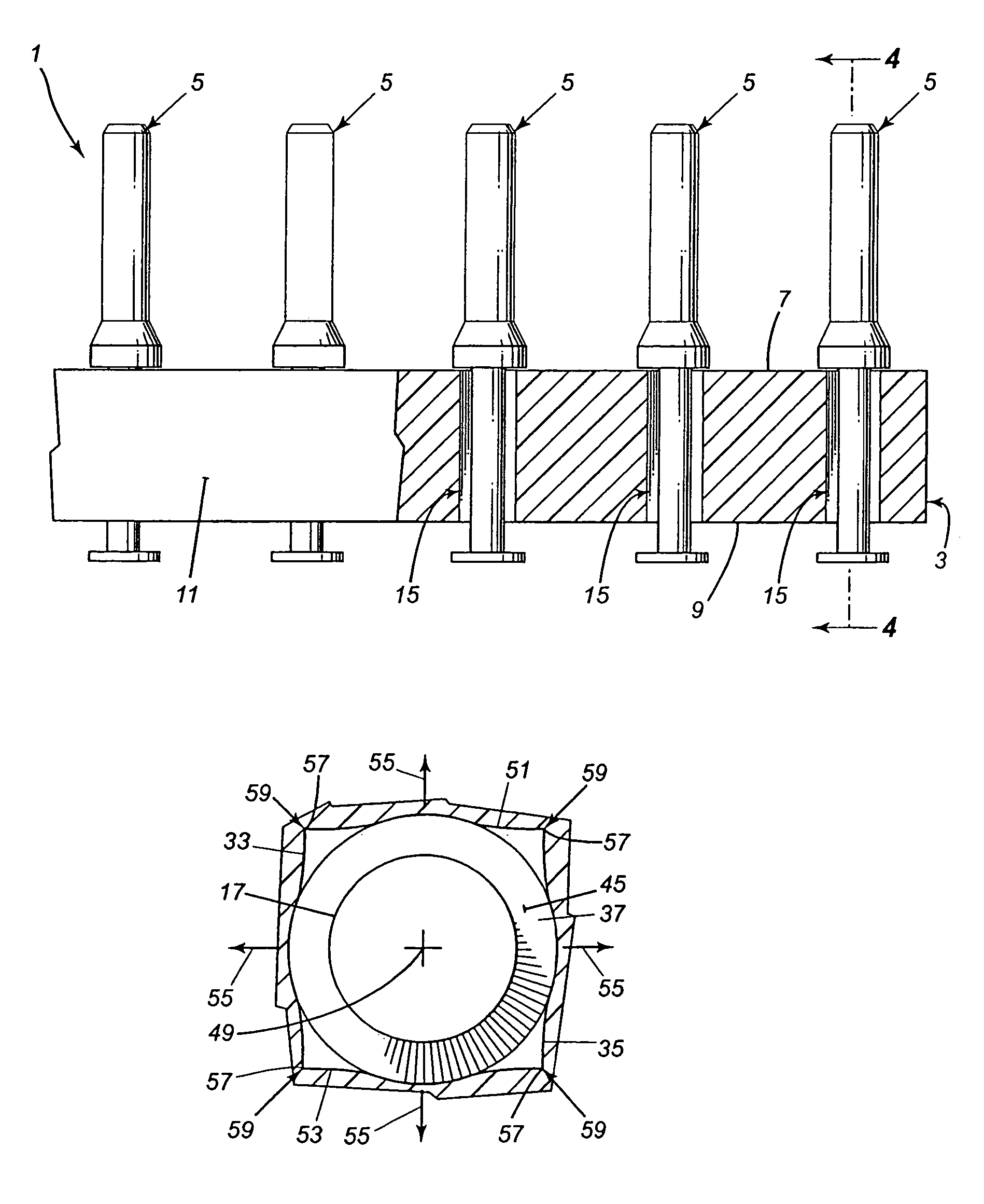
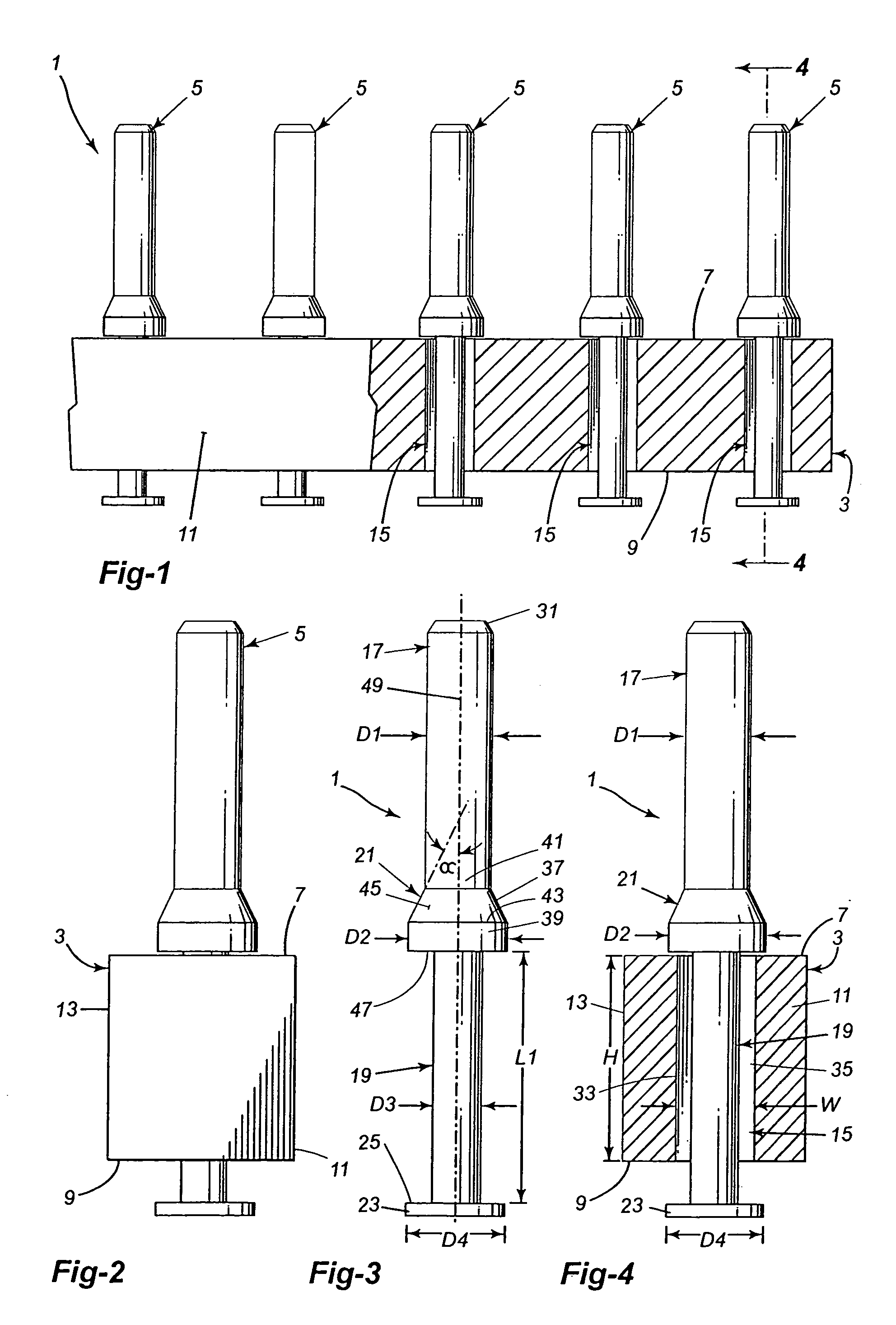
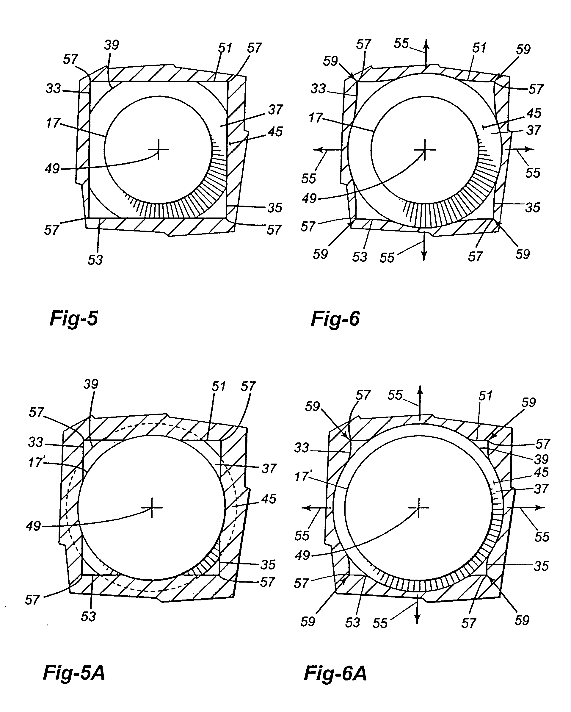
[0022]The electrical connector as shown in FIGS. 1 and 2, has a carrier 3 with a plurality of contact pins 5 mounted on the carrier. The carrier 3 has a rectangular cross-sectional shape with the short sides of the shape forming the top and bottom sides 7, 9 of the carrier and the long sides forming the vertical sides 11, 13 of the carrier. A series of contact pin mounting holes 15 extend through the carrier 3 between its top and bottom sides 7, 9. The holes 15 are normally equally spaced apart along the length of the carrier 3 and are normally centered between the vertical sides 11, 13 of the carrier. In accordance with the present invention, the holes 15 have a square cross-sectional shape. While the carrier 3 has been described as having a rectangular cross-sectional shape it could have other shapes as well.

[0023]The contact pins 5 are generally cylindrical in shape. Each pin 5, as shown in FIGS. 3 and 4, has a leading pin section 17, and a trailing pin section 19. Retaining mean...


PUM


Abstract

An electrical connector having an electrically non-conductive carrier, the carrier having a plurality of contact pin mounting holes extending there through. Each hole has a square cross-section. An electrically conductive contact pin is passed through each hole. A retainer is provided on the pin separating a leading pin section from a trailing pin section. The trailing pin section has a length slightly longer than the length of the hole and a diameter slightly less than the width of the hole. The retainer and the contact head both have a diameter at least slightly greater than the width of the hole to retain the pin in the hole. An electrical contact pin for use with such a multi-pin electrical connector, a method of inserting such contact pin may be provided.

Description

CROSS-REFERENCE TO RELATED APPLICATIONS[0001]This application claims the priority of Canadian application no. 2,453,637, filed Dec. 18, 2003, which is incorporated herein by reference.FIELD OF THE INVENTION[0002]This invention is directed toward an electrical connector and more particularly toward a multi-pin electrical connector to be surface mounted on a printed circuit board (PCB). The invention is also directed toward contact pins used with the electrical connector and to a method of assembling the connector.BACKGROUND ART[0003]Multi-pin electrical connectors for PCB surface mount technology are known. The connector has a support or carrier with a plurality of circular pin mounting holes extending through the carrier. The holes are usually in a straight line along the length of the carrier. The carrier is electrically non-conductive. A contact pin, generally cylindrical in shape, is mounted in each hole Each contact pin has a contact head on one side of the carrier and projects ...

Claims


Application Information

Patent Timeline
Patent Type & Authority Patents(United States)
IPC IPC(8): H01R12/00H01R12/51H01R12/50H01R13/03H01R13/631
CPCH01R12/57H01R13/6315H01R12/714H01R13/03
Inventor XU, PEI REN
Owner 7195087 CANADA INC
Why Eureka
Try Eureka