Osmotic pump with means for dissipating internal pressure

a technology of osmotic pump and internal pressure, which is applied in the field of implantable osmotic pump, can solve the problems of preventing the separation of semi-permeable membranes, reducing the pressure within the pump, and dissipating internal pressure before one or more components of the osmotic pump, so as to reduce the internal pressure, reduce the likelihood, and be convenient to design

Active Publication Date: 2007-04-24
INTARCIA THERAPEUTICS INC
View PDF71 Cites 132 Cited by
  • Summary
  • Abstract
  • Description
  • Claims
  • Application Information

AI Technical Summary

Benefits of technology

[0008]The vent included in an osmotic pump of the present invention is formed through the reservoir of the osmotic pump and is positioned such that the vent is sealed from the osmotic composition under normal operating conditions. However, the vent is also positioned in the reservoir such that, if the pressure within the osmotic pump reaches a magnitude that results in displacement of one or more components, the vent is opened or exposed to the materials forming the osmotic composition, which allows release of materials forming the osmotic composition into the environment of operation and results in the dissipation of the internal pressure before one or more components of the osmotic pump fails or is separated from the device. In addition, because an osmotic pump according to the present invention can be designed without compressive elements, the maximum rate of material expulsion from the vent will typically match the targeted release rate of the osmotic pump. Therefore, an osmotic pump according to the present invention can be easily designed to allow venting of the osmotic composition, while reducing or minimizing the likelihood that such venting will result in discomfort or irritation to the subject.
[0009]In a preferred embodiment, an osmotic pump includes a vent that is sealed by the semipermeable membrane of the osmotic pump during normal operating conditions. The semipermeable membrane of such an embodiment is friction fit within the reservoir and is designed to allow progressive displacement of the semipermeable membrane once a threshold pressure is reached within the osmotic pump. The vent included in this embodiment of the present invention is positioned such that, if the internal pressure reaches the threshold pressure and the semipermeable membrane begins to be displaced relative to the reservoir, the vent is exposed well before the semipermeable membrane is separated from the device. Once the vent is exposed, the osmotic materials included in the osmotic composition may be expelled from the osmotic pump, resulting in a decrease in pressure within the pump and preventing separation of the semipermeable membrane.

Problems solved by technology

However, the vent is also positioned in the reservoir such that, if the pressure within the osmotic pump reaches a magnitude that results in displacement of one or more components, the vent is opened or exposed to the materials forming the osmotic composition, which allows release of materials forming the osmotic composition into the environment of operation and results in the dissipation of the internal pressure before one or more components of the osmotic pump fails or is separated from the device.
Once the vent is exposed, the osmotic materials included in the osmotic composition may be expelled from the osmotic pump, resulting in a decrease in pressure within the pump and preventing separation of the semipermeable membrane.

Method used


Image

  • Osmotic pump with means for dissipating internal pressure
  • Osmotic pump with means for dissipating internal pressure

Examples


Embodiment Construction

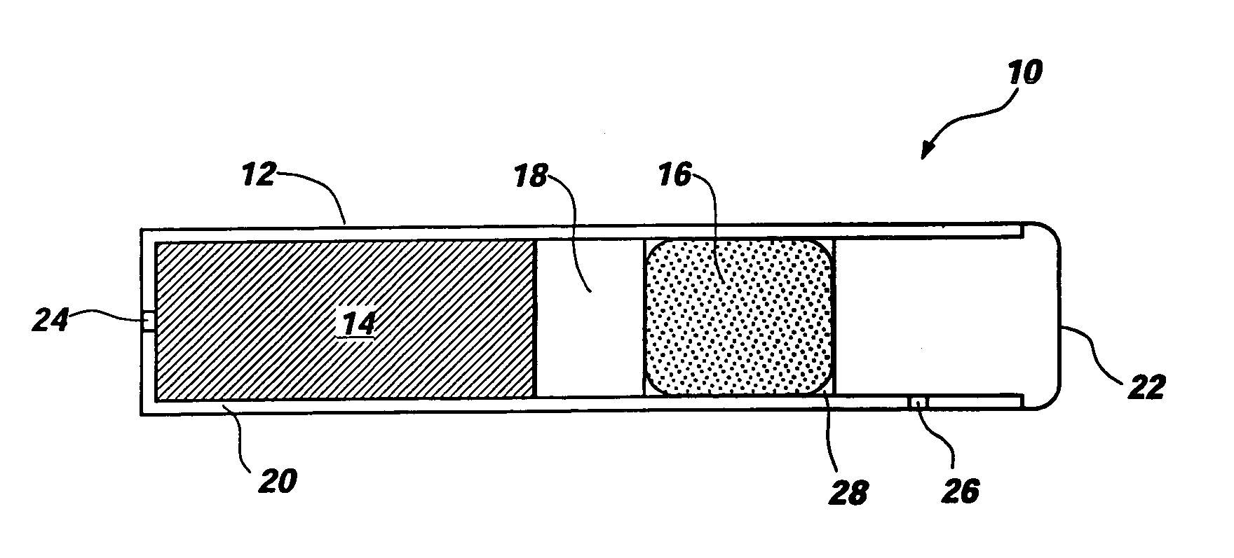
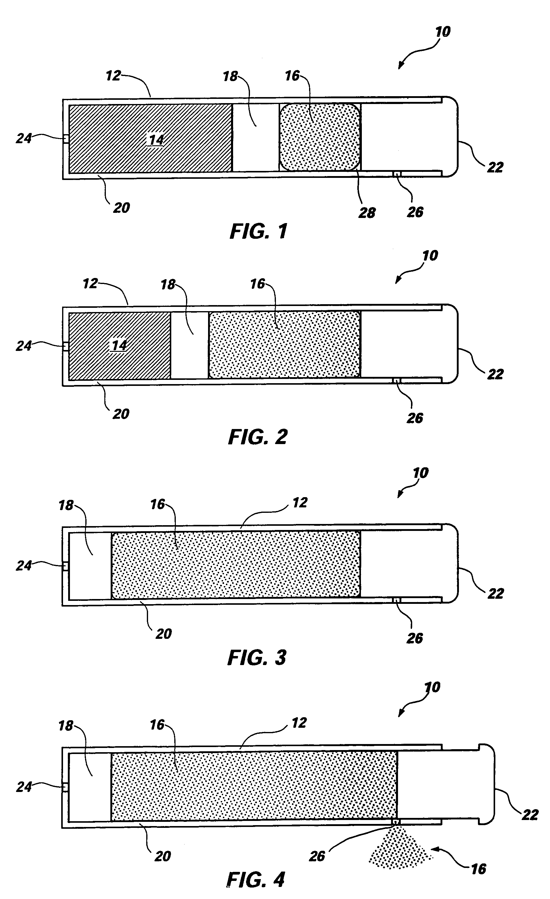
[0015]An osmotic pump 10 according to the present invention is illustrated in FIG. 1. As can be seen by reference to these figures, an osmotic pump 10 according to the present invention includes a reservoir 12, a drug formulation 14, an osmotic composition 16, a piston 18, a semipermeable membrane 22, a delivery orifice 24, and a vent 26 formed through the wall 20 of the reservoir 12. However, the configuration of the osmotic pump 10 illustrated in FIG. 1 provides only one example of an osmotic pump according to the present invention and is not to be construed as limiting the present invention. The present invention is generally applicable to osmotic pumps, and an osmotic pump according to the present invention may be designed to conform to a wide range of desired sizes or shapes. Moreover, an osmotic pump according to the present invention may be designed for application in various environments or administration by various routes, such as by oral administration, ruminal administrat...


PUM


Abstract

The present invention includes an osmotic pump that includes a means for venting an osmotic composition included in the pump before the internal pressure of the pump has the opportunity to build to such an extent that the pump is structurally compromised, such as when one or more components of the pump are physically separated. The means for venting osmotic material included in an osmotic pump according to the present invention includes a vent that allows the material included in the osmotic composition of the pump to dissipate into an environment of operation at a rate that results in dissipation of the pressure created within the osmotic pump and a reduced potential for subject discomfort or irritation.

Description

CROSS-REFERENCE TO RELATED APPLICATION[0001]Pursuant to the provisions of 35 U.S.C. § 119(e), this application claims the benefit of the filing date of provisional patent application Ser. No. 60 / 459,296, filed Mar. 31, 2003, for “Osmotic Pump With Means For Dissipating Internal Pressure.”FIELD OF THE INVENTION[0002]The present invention relates to implantable osmotic pumps providing sustained delivery of a drug. In particular, the present invention is directed to an implantable osmotic pump including a vent that allows gradual venting of osmotic material after the drug formulation included in the osmotic pump is delivered.BACKGROUND[0003]Implantable, controlled-release osmotic pumps (hereinafter “osmotic pumps”) are known in the art. For example, U.S. Pat. Nos. 3,797,492, 3,987,790, 4,008,719, 4,865,845, 5,057,318, 5,059,423, 5,112,614, 5,137,727, 5,151,093, 5,234,692, 5,234,693, 5,279,608, 5,336,057, 5,728,396, 5,985,305, 5,997,527, 5,997,902, 6,113,938, 6,132,420, 6,217,906, 6,261...

Claims


Application Information

Patent Timeline
Patent Type & Authority Patents(United States)
IPC IPC(8): A61K9/22A61F13/00A61K9/00A61M5/145A61M31/00
CPCA61K9/0004A61M31/002A61M2005/14513A61M31/00A61K9/00
Inventor DIONNE, KEITH E.MOSBAUER, ROBERTDAVIS, CRAIG R.PEERY, JOHN R.
Owner INTARCIA THERAPEUTICS INC
Why Eureka
Try Eureka