Fuel container

a fuel container and container body technology, applied in the field of fuel containers, can solve the problems of insufficient suppression of gasoline permeation amount, easy permeation of stored liquid gasoline and/or vaporized gasoline through the polyethylene walls into the atmosphere, and high barrier properties, and suppress fuel permeation. , the effect of excellent impact resistan

Inactive Publication Date: 2007-04-24
KURARAY CO LTD
View PDF25 Cites 8 Cited by
  • Summary
  • Abstract
  • Description
  • Claims
  • Application Information

AI Technical Summary

Benefits of technology

[0032]Therefore, the present invention described herein makes possible the objectives of; providing a fuel container having high barrier properties with respect to the fuel, for example gasoline, contained in the container; providing a blow-molded fuel container which sufficiently suppresses fuel permeation at a pinch-off part of the container, and in which the pinch-off part has sufficient contact strength, resulting in an excellent impact resistance; and providing a fuel container that effectively suppresses the fuel permeation at a bonding portion at which a component is attached to the container.

Problems solved by technology

However, it is known that fuel tanks made of polyethylene have a disadvantage that the stored liquid gasoline and / or the vaporized gasoline easily permeates through the polyethylene walls into the atmosphere.
However, in the manufacture of fuel containers according to these methods, the gasoline permeation amount cannot be suppressed sufficiently.

Method used


Image

  • Fuel container
  • Fuel container
  • Fuel container

Examples


example 1

[0189]For the thermoplastic resin (B), the high-density polyethylene (HDPE) BA-46-055 (having a density of 0.970 g / cm3, and a MFR of 0.03 g / 10 min at 190° C. and 2160 g) by Paxon was used; for the adhesive resin (D), ADMER GT-6A (having a MFR of 0.94 g / 10 min at 190° C. and 2160 g) by Mitsui Chemicals, Inc. was used; and for the barrier resin (A), an ethylene-vinyl alcohol copolymer including 32 mol % of ethylene and having a degree of saponification of 99.5 mol %, and having a MFR of 1.3 / 10 min at 190° C. and 2160 g was used. Using these resins, a fuel tank was obtained by blow-molding with a blow-molding machine TB-ST-6P by Ski Tetsukousho according to the following steps. (The molding in the following examples and comparative examples was performed with the same blow-molding machine.) A three-resin five-layered parison with the structure (inner layer) HDPE / Tie / Barrier / Tie / HDPE (outer layer) was extruded at 210° C. (“HDPE” denotes an high-density polyethylene layer, “Tie” denotes ...

example 3

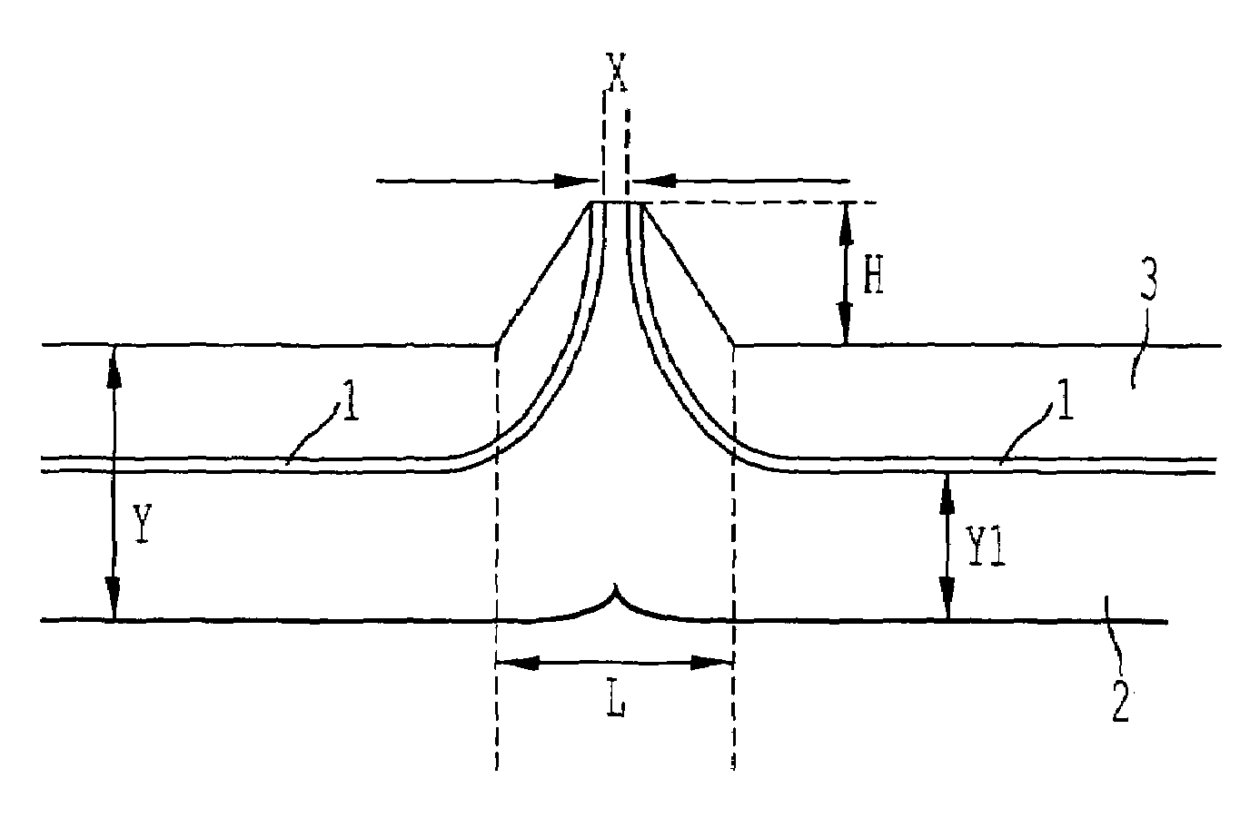
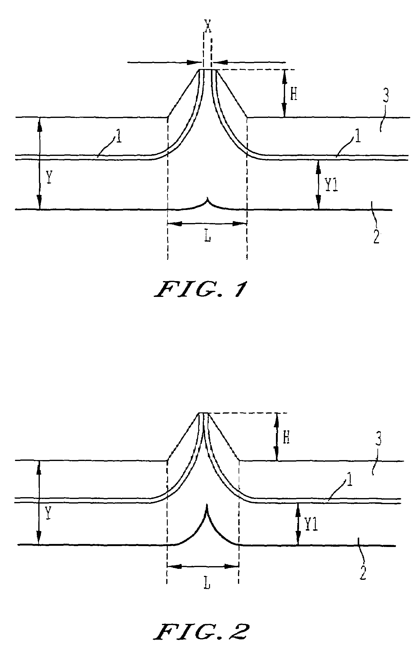
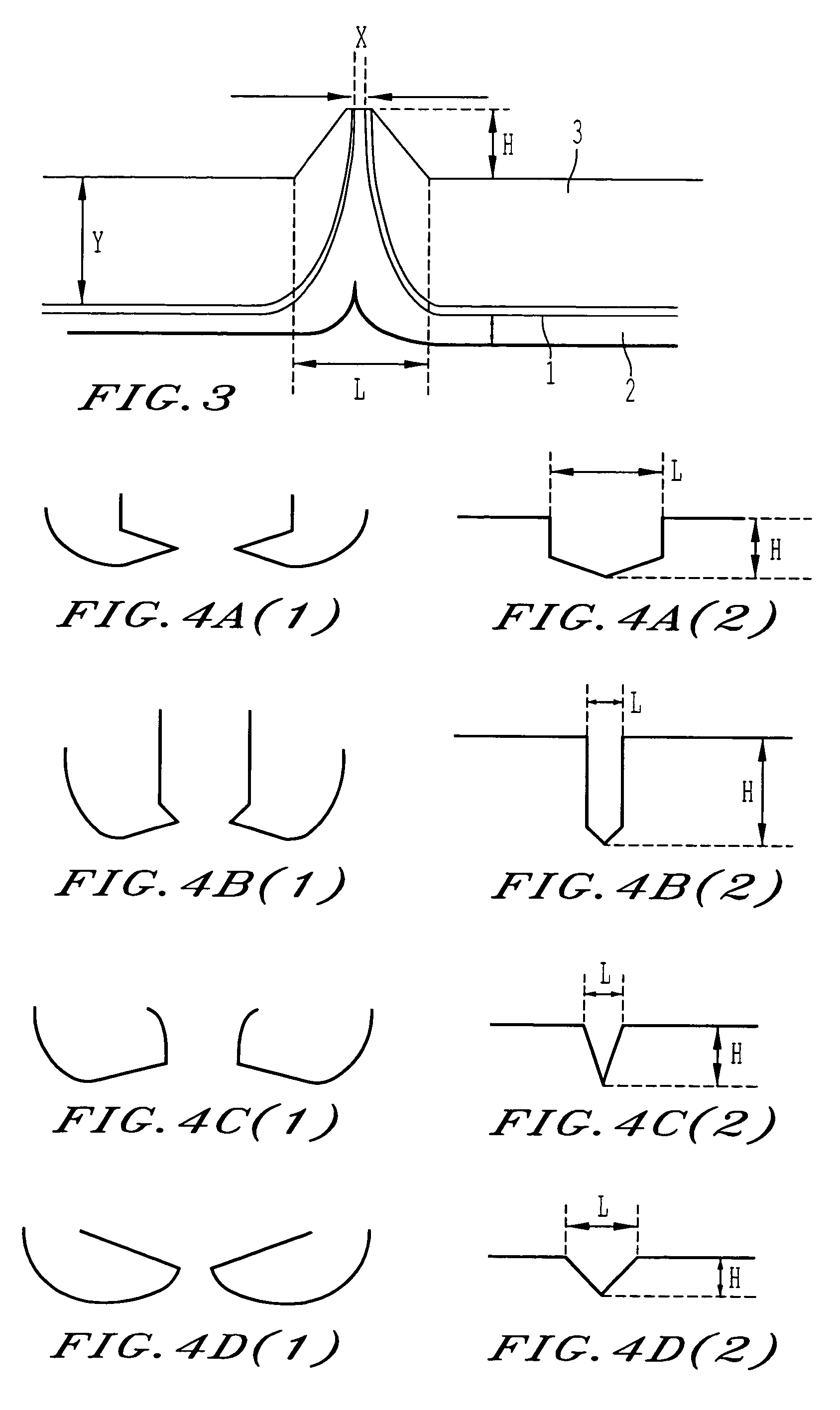
[0196]For the thermoplastic resin (B), the adhesive resin (D) and the barrier resin (A), the same resins as the ones in Example 1 were used. Moreover, as a recovered resin, a resin mixture obtained by crushing a tank made in accordance with Example 1 was used. Using these resins, a fuel tank was obtained by blow-molding according to the following steps. A four-resin six-layered parison with the structure (inner layer) HDPE / Tie / Barrier / Tie / recovered layer / HDPE (outer layer) was extruded at 210° C. Then, molding was performed at a mold-cramping force of 3 tons with a mold having a pinch-off part forming section as shown in FIG. 4a. Blowing was performed in the mold at 15° C., such that the ratio (Y / Y) of the distance (X) between end portions of the barrier layer and the average thickness (Y) of the container body was 4 / 1000, the ratio (H / L) between height and length of the pinch-off part was 0.5, and the ratio (Y1 / Y) between the total thickness (Y1) of the layers of the container body...

example 5

[0204]For the thermoplastic resin (B), the adhesive resin (D) and the barrier resin (A), the same resins as the ones in Example 1 were used. Moreover, as a recovered resin, a resin e obtained by crushing a tank made in accordance with Example 1 was uses Using these resins, a fuel tank was obtained by blow-molding according to the following steps. A four-resin seven-layered parison with the structure (inner layer) HDPE / recovered layer / Tie / Barrier / Tie / recovered layer / HDPE (outer layer) was extruded at 210° C. Then, molding was performed at a mold-cramping force of 3 tons with a mold having a pinch-off part forming section as shown in FIG. 4a. Blowing was performed in the mold at 15° C., such that the ratio (X / Y) of the distance (X) between end portions of the barrier layer and the average thickness (Y) of the container body was 4 / 1000, the ratio (H / L) between height and length of the pinch-off part was 0.5, and the ratio (Y1 / Y) between the total thickness (Y1) of the layers of the con...


PUM

PropertyMeasurementUnit
absolute temperaturesaaaaaaaaaa
melting pointaaaaaaaaaa
RHaaaaaaaaaa

Abstract

A fuel container with high fuel barrier properties is provided. The fuel container is a coextrusion blow-molded fuel container having a container body made of a layered structure. The layered structure comprises: a barrier layer made of a barrier resin (A); and an inner layer and an outer layer made of a thermoplastic resin (B) that is different from the barrier resin (A); wherein a ratio (X / Y) of a distance (X) between end portions of the barrier layer at a pinch-off part of the fuel container and an average thickness (Y) of the container body is at least 1 / 10000 and at most 1 / 10; and wherein a ratio (Y1 / Y) between a total thickness (Y1) of the layers of the container body that are located on the inside with respect to the barrier layer and an average thickness (Y) of the container body is at least 3 / 10 and at most 7 / 10.

Description

BACKGROUND OF THE INVENTION[0001]1. Field of the Invention[0002]The present invention relates to a fuel container having high gasoline barrier properties.[0003]2. Description of the Related Art[0004]In recent years, coextrusion blow-molded containers made of plastic materials are preferably used for containers for storing fuels, such as gasoline, and examples for such containers are the fuel tanks of motor vehicles. As for the plastic material used as the material of such containers, there are high expectations in polyethylene (especially very high-density polyethylene) with regard to economic efficiency, molding processability, mechanical strength, and the like. However, it is known that fuel tanks made of polyethylene have a disadvantage that the stored liquid gasoline and / or the vaporized gasoline easily permeates through the polyethylene walls into the atmosphere.[0005]To eliminate this disadvantage, a method is known in which a halogen gas (e.g. fluorine, chlorine, or bromine) ...

Claims


Application Information

Patent Timeline
Patent Type & Authority Patents(United States)
IPC IPC(8): B29D22/00B29D23/00B32B1/08B67D99/00B32B27/08
CPCB32B1/02B32B3/266B32B3/30B32B27/08B60K15/03177B32B3/263Y10T428/1359B32B2250/03B32B2250/24B32B2274/00B32B2307/558B32B2307/7265B32B2439/40B32B2605/00B60K2015/03046B60K2015/0346Y10T428/13Y10T428/1383Y10T428/1379Y10T428/1355Y10T428/24777Y10T428/1352Y10T428/24273B67D99/00B32B2323/043B32B27/32B32B2439/00B32B27/304B32B27/306B32B15/08B32B7/12B32B2363/00B32B27/288B32B27/38B32B27/34B32B2377/00
Inventor MICHIHATA, KEIZOHAYASHI, NAHOTO
Owner KURARAY CO LTD
Why Eureka
Try Eureka