Power management system for a floor care appliance

a power management system and floor care technology, applied in the field of floor care, can solve the problem of little versatility in configuring the circuit according to different parameters

Active Publication Date: 2007-04-24
HOOVER LIMITED
View PDF17 Cites 43 Cited by
  • Summary
  • Abstract
  • Description
  • Claims
  • Application Information

AI Technical Summary

Benefits of technology

[0013]In an alternate preferred embodiment of the invention, a floor care appliance having a programmable microprocessor is provided wherein the microprocessor is programmed to store operational parameters of the appliance as well as real time performance data. The microprocessor is capable of being connected to a network wherein the programmed operational parameters may be changed through a remote interface connected to the network and the real time performance data uploaded to the interface. The performance data can then be evaluated to determine the operating condition of the cleaner for repair and maintenance purposes. The performance data may also be used to determine adjustments to be made to the operating parameters of the appliance which are downloaded to the microprocessor over the network.

Problems solved by technology

In addition due to the circuit being designed with analog devices, there is little versatility in configuring the circuit according to different parameters.

Method used


Image

  • Power management system for a floor care appliance
  • Power management system for a floor care appliance
  • Power management system for a floor care appliance

Examples


Embodiment Construction

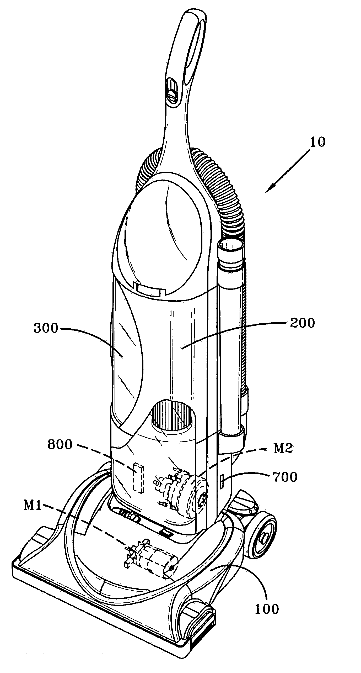
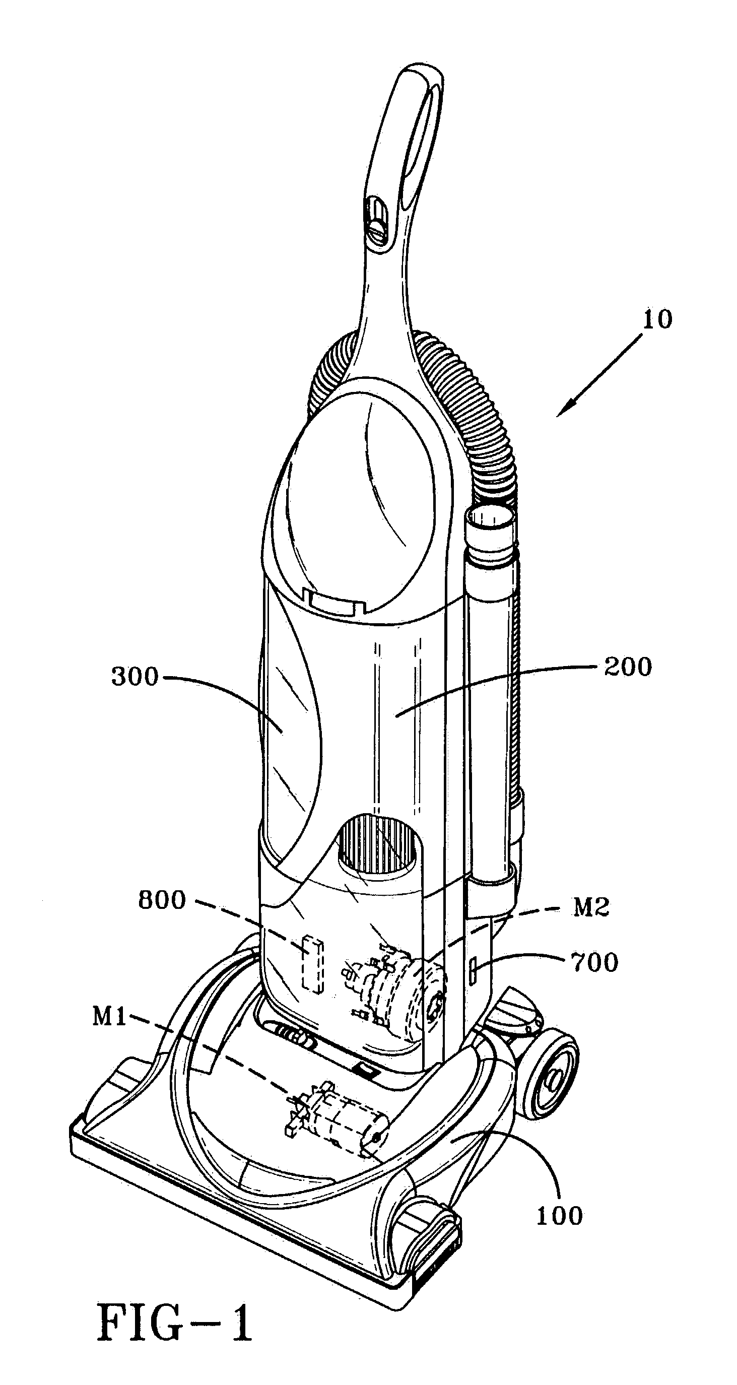
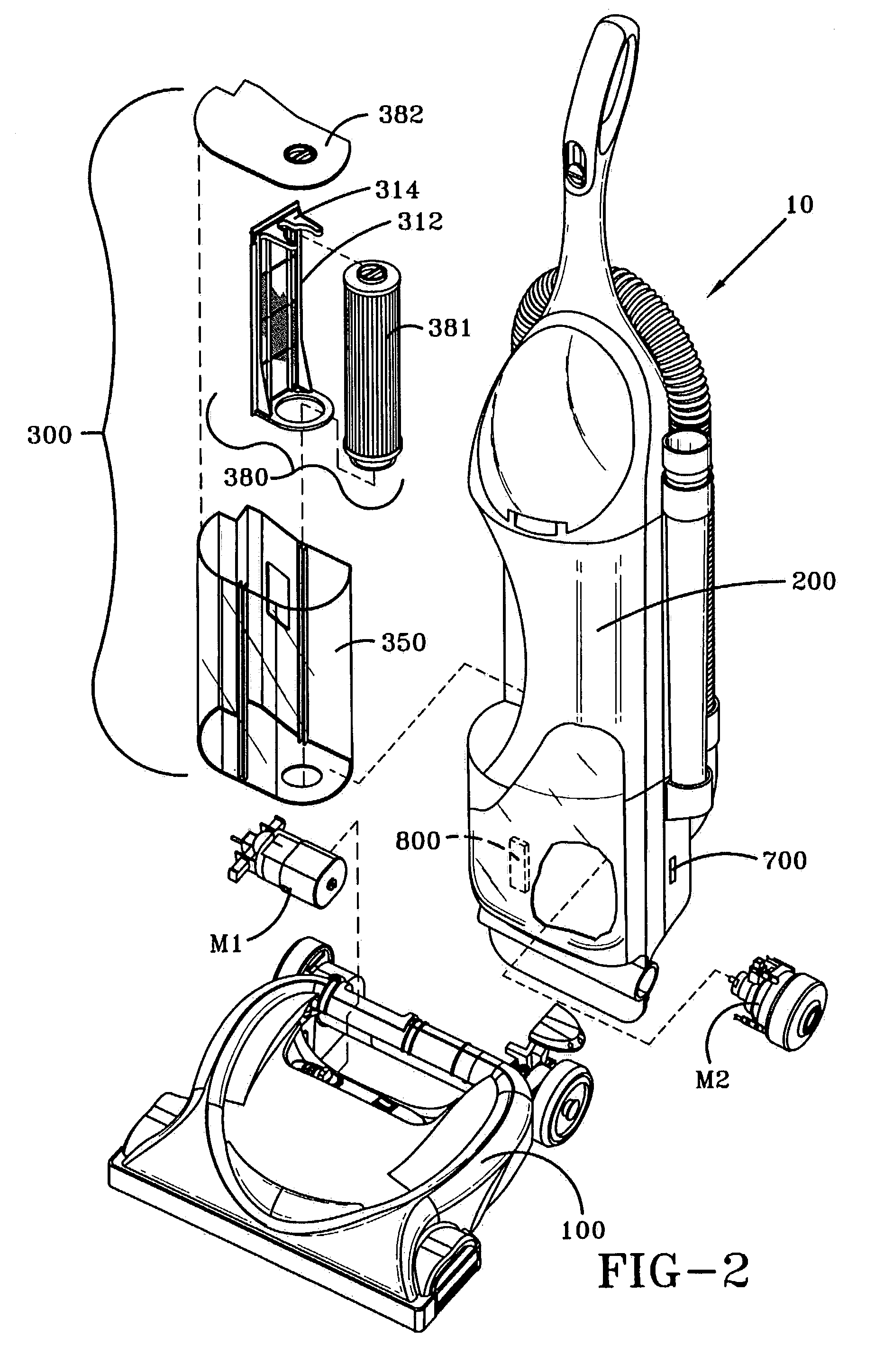
[0018]Referring now to FIGS. 1 and 2, shown is an upright vacuum cleaner 10 having an improved power management system 500. Upright vacuum cleaner 10 includes a foot 100 and an upper housing assembly 200 pivotally connected to foot 100. Foot 100 is similar to those known in the art and includes a nozzle opening (not shown) for receiving a stream of dirt-laden air and an agitator (not shown) for agitating and loosening dust and debris from a floor surface when upright vacuum cleaner 10 is in the floorcare mode. Foot 100 further includes a pair of front wheels (not shown) rotatably mounted on a wheel carriage (not shown), and a pair of rear wheels 130.

[0019]Located in foot 100 or upper housing 200 is a motor-fan assembly M2 which creates the suction necessary to remove the loosened dust and debris from the floor surface. The motor-fan assembly M2 fluidly connects to foot or suction nozzle 100 by a dirt duct (not shown). The upper housing assembly 200 houses a particle filtration and c...


PUM


Abstract

A floor care appliance is provided with an improved power management system for controlling the total amount of current provided to at least a first and a second load device of an appliance. The power management system is comprised of a microprocessor, an alternating current voltage source, a voltage regulating circuit, a clamping circuit, at least two load devices, and a MOC and a triac for each of the at least two load devices. The clamping circuit outputs a fixed voltage of 5.7 volts during the positive portion of the ac cycle and a fixed voltage of −0.7 volts during the negative portion of the ac cycle. The fixed voltages are input to a microprocessor which utilizes these inputs to control the average voltage and the amount of time the current is turned on to each of the at least first and second load devices. A current sensing circuit is used to monitor the current to one of the at least two load devices to provide feedback to the microprocessor so that the microprocessor can adjust the average voltage and current to the at least two load devices so that the total current consumed does not exceed a pre-determined level.

Description

BACKGROUND OF THE INVENTION[0001]1. Field of the Invention[0002]This invention relates to floor care, and more specifically, to a floor care appliance having a power management system for limiting the total current the load devices of the appliance can consume.[0003]2. Summary of the Prior Art[0004]Floor care appliances are well known in the art. Typical floor care appliances include upright vacuum cleaners, canister vacuum cleaners, hard floor cleaners, and extractors. It is known to provide floor care appliances with power management systems for managing the current providing to various load devices such as the motor-fan assembly and / or an agitator drive motor.[0005]For example, in U.S. Pat. No. 5,747,973 issued to Robitaille et al. there is provided a regulating switch circuit for conditioning operation of a first load upon operation of a second load wherein the first load and the second load consume electrical energy from a power source. The circuit includes a detecting means fo...

Claims


Application Information

Patent Timeline
Patent Type & Authority Patents(United States)
IPC IPC(8): H02P5/00A47L5/00H02P1/54H02M5/257H02P5/46
CPCA47L9/2831A47L9/2842A47L9/2857H02M5/2576H02P5/46H02M2001/009Y02B40/82H02M1/009Y02B40/00G05F1/455
Inventor TONDRA, AARON P.GORDON, EVAN A.SCLAFANI, ADAM C.
Owner HOOVER LIMITED
Why Eureka
Try Eureka