Mobile phone antenna

a mobile phone and antenna technology, applied in the direction of resonant antennas, elongated active elements, radiating element structural forms, etc., can solve the problems of affecting the operation of the antenna, the antenna is not easy to be integrated with other circuitry systems and associated components, and the corresponding operating bandwidth is quickly degraded

Active Publication Date: 2007-04-24
NAT SUN YAT SEN UNIV +1
View PDF6 Cites 35 Cited by
  • Summary
  • Abstract
  • Description
  • Claims
  • Application Information

AI Technical Summary

Benefits of technology

[0012]The mobile phone antenna according to the present invention mainly utilizes the antenna ground plane as a metal shielding wall to accomplish a seamless integration between the antenna and the shielding metal box of the RF module and RF circuitry without the need of an isolation distance.

Problems solved by technology

However, in the existing communication products, especially those with an embedded antenna, the internal spacing for antenna is usually very limited.
Thus, with this spacing limitation, how to achieve good antenna performances and good electromagnetic compatibility with nearby electronic components inside the product has become one of the major design challenges for the final communication product.
The drawback of this conventional antenna design, however, is that the antenna is not easy to be integrated with other circuitry systems and associated components.
The drawback of this conventional mobile phone antenna is that with a decrease in d (that is, by moving the shielding metal box 15 close to the metal plate 11), the corresponding operating bandwidth is quickly degraded and thus can not cover the required UMTS band.
With this design configuration, the internal spacing utilization and design flexibility have become limited for this type of conventional mobile phone antenna

Method used


Image

  • Mobile phone antenna
  • Mobile phone antenna
  • Mobile phone antenna

Examples


Embodiment Construction

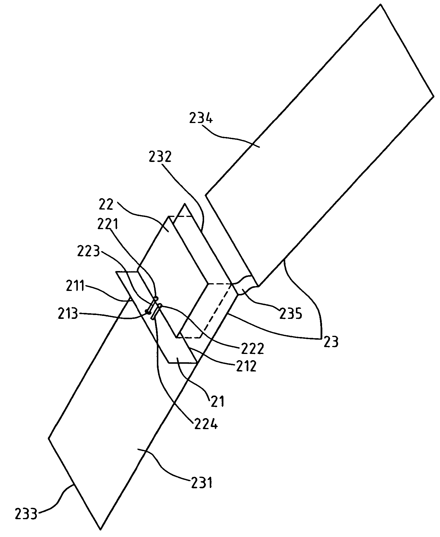
[0026]FIG. 2A illustrates a schematic view of a first embodiment of the present invention. Referring to FIG. 2A, the mobile phone antenna comprises one antenna ground plane 21, one radiating conducting plate 22, one feeding conducting strip 223, one shorting conducting strip 224, and one system ground plane 23. The antenna ground plane 21 includes one first long side 211 and one second long side 212. The radiating conducting plate 22 is installed perpendicularly to the top of the antenna ground plane 21. The radiating conducting plate 22 includes one feeding point 221 and one shoring point 222. The feeding conducting strip 223 is installed between the antenna ground plane 21 and the radiating conducting plate 22. The feeding conducting strip has two ends, which is electrically connected to the feeding point 221 on the radiating conducting plate 22 and to a feeding signal source, respectively, so that the feeding signal can be fed into the radiating conducting plate 22. The shorting ...


PUM


Abstract

The present invention provides a mobile phone antenna, which comprises an antenna ground plane, a radiating conducting plate, a feeding conducting strip, a shorting conducting strip, and a system ground plane. Using the antenna ground plane as a shielding metal wall, the present invention advantages itself of making the antenna and a shielding metal box easier to be integrated without a need for an isolation distance. The present invention thus makes the best use of the internal spacing of a mobile phone. This antenna is suitable for application as an embedded antenna for both folded-type and bar-type mobile phones. The operating bandwidth of this antenna can cover the required bandwidth for a Universal Mobile Telecommunication System operation.

Description

FIELD OF THE INVENTION[0001]The present invention generally relates to an antenna, and more specifically to a mobile phone antenna.BACKGROUND OF THE INVENTION[0002]Following the global blooming in mobile communications, various kinds of handheld communication products have been demanded by wireless users. One of the major demands is to minimize the product dimensions. Generally speaking, the dimensions of a communication product can be effectively minimized by using an embedded antenna inside the communication product. However, in the existing communication products, especially those with an embedded antenna, the internal spacing for antenna is usually very limited. Thus, with this spacing limitation, how to achieve good antenna performances and good electromagnetic compatibility with nearby electronic components inside the product has become one of the major design challenges for the final communication product.[0003]For conventional planar inverted-F antennas (PIFAs) applied to mo...

Claims


Application Information

Patent Timeline
Patent Type & Authority Patents(United States)
IPC IPC(8): H01Q1/24
CPCH01Q1/243H01Q9/40
Inventor TANG, CHIA-LUNWONG, KIN-LUSU, SAOU-WEN
Owner NAT SUN YAT SEN UNIV
Why Eureka
Try Eureka