Liquid crystal display module and fastening structure thereof

a technology of liquid crystal display and fastening structure, which is applied in the direction of instruments, non-linear optics, optics, etc., can solve the problems of very hard rework, and achieve the effect of reducing the work required for assembling and reducing the working tim

Inactive Publication Date: 2007-04-24
HANNSTAR DISPLAY CORPORATION
View PDF1 Cites 78 Cited by
  • Summary
  • Abstract
  • Description
  • Claims
  • Application Information

AI Technical Summary

Benefits of technology

[0007]An objective of the present invention is to provide an LCD module and fastening structure thereof, wherein a pair of locking mechanisms is installed on the edge of the first frame and the second frame and can be used for joining them together. Hence, it can provide a fastening structure for assembling the frames conveniently so as to reduce the work required for assembling them, thereby reducing the working time. Moreover, during the assembly process, no tools are required for assembling.

Problems solved by technology

Moreover, the screws get stripped readily during assembling, making rework very hard.

Method used


Image

  • Liquid crystal display module and fastening structure thereof
  • Liquid crystal display module and fastening structure thereof
  • Liquid crystal display module and fastening structure thereof

Examples


first embodiment

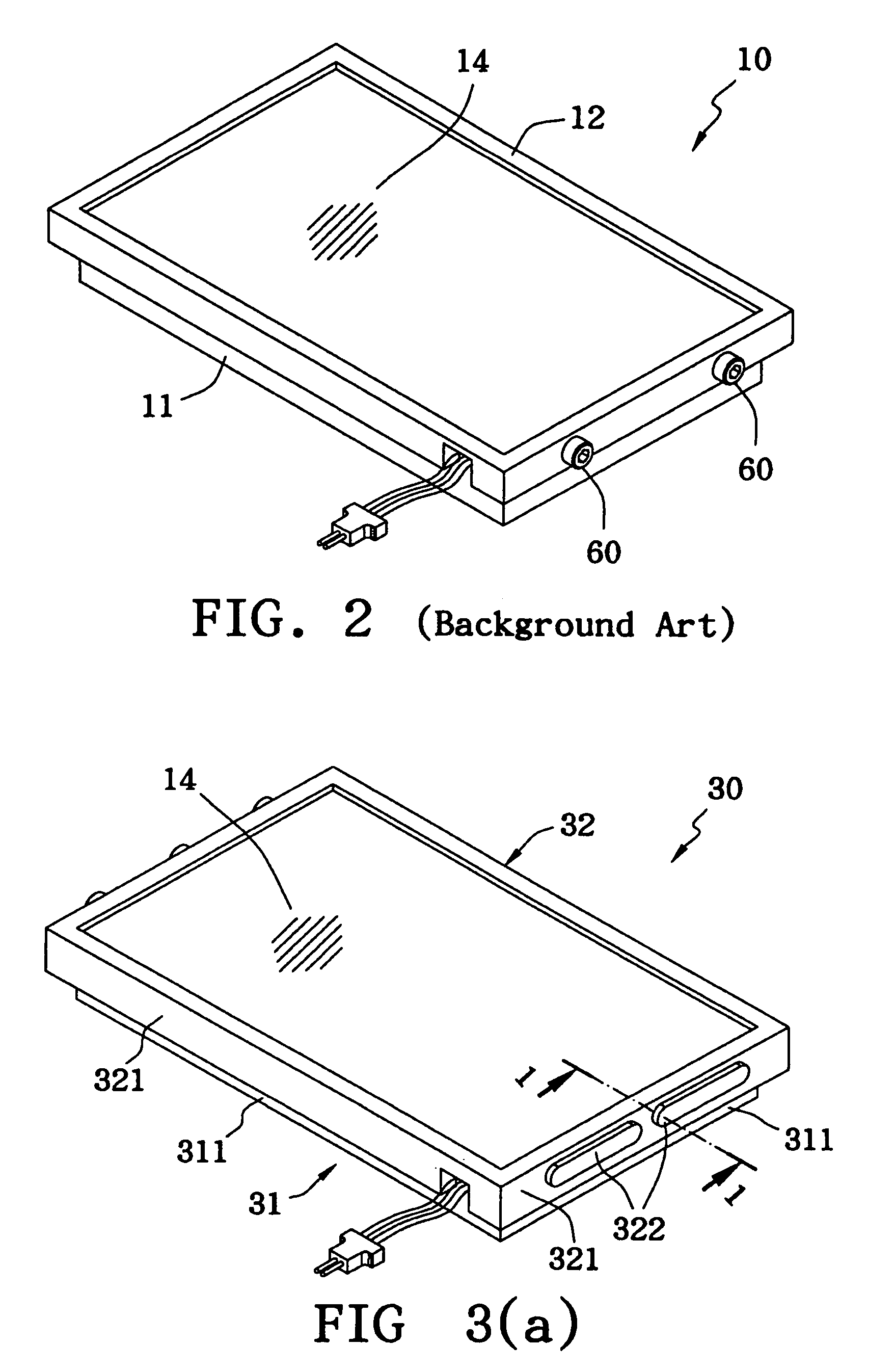
[0016]FIG. 3(a) is a perspective diagram of the LCD module 30 in accordance with the present invention. The side 321 of a second frame 32 covers the side 311 of a first frame 31. A pair of locking mechanisms formed on the two sides 321 and 311 respectively is used to join the second frame 32 and the first frame 31 closely together. The pair of locking mechanisms can fasten the frames 31, 32 and the LCD cell 14 together by engaging the protrusion of one frame with the hollow of another frame, without the need to use the other fastening parts, such as screws and bolts.

[0017]FIG. 3(b) is a cross-section diagram along the line 1—1 of the LCD module 30 in FIG. 3(a). The first frame 31 supports the base of a back light module 13 with its four sides 311 extending upward the LCD cell 14 is superimposed on the back light module 13. First locking mechanisms 312 as protrusions are formed on the sides 311 of the first frame 31, and are interlocked with the second locking mechanisms 322 as hollo...

second embodiment

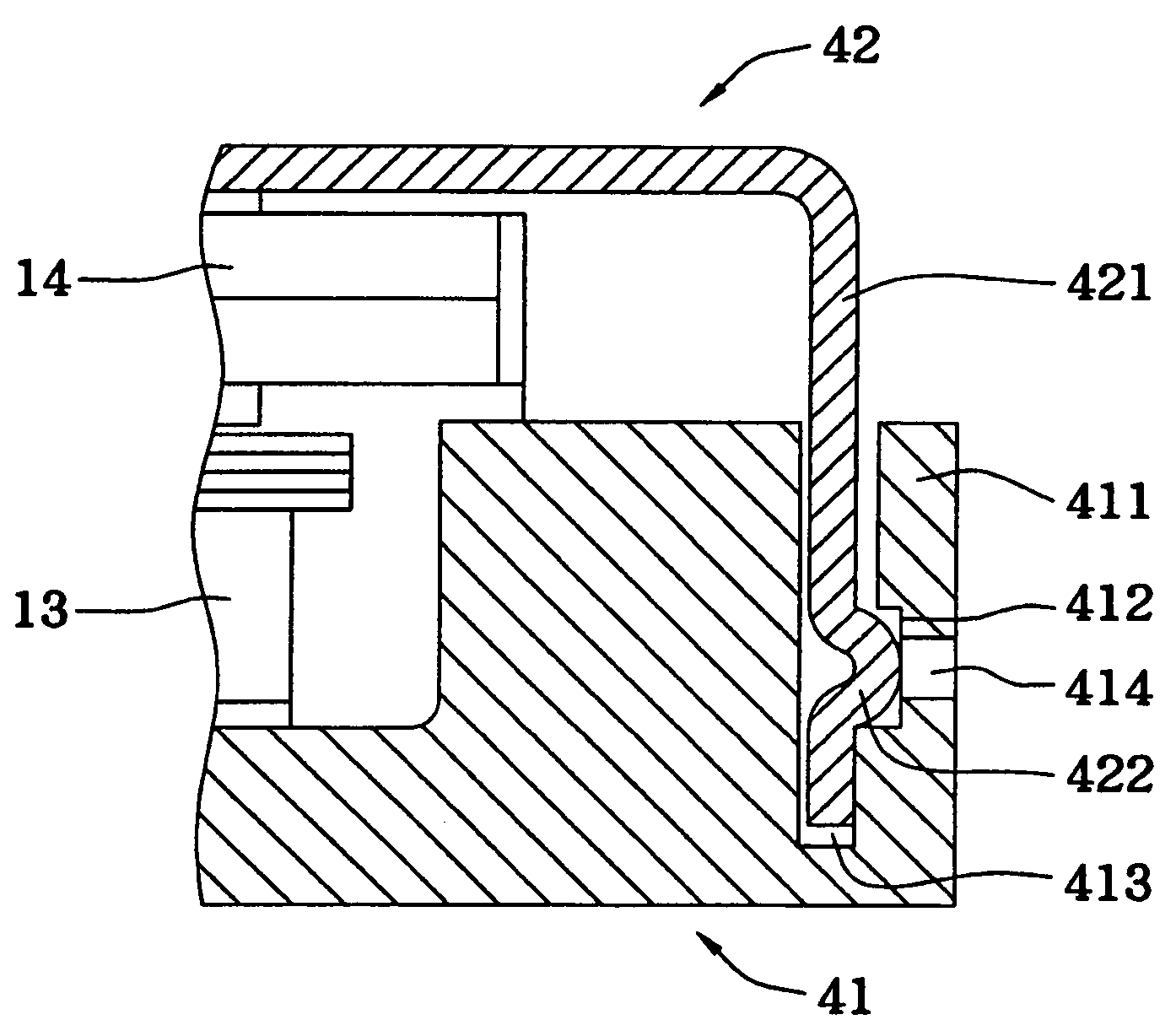
[0023]FIG. 4(a) is a perspective diagram of the LCD module 40 in accordance with the present invention. The side 421 of the second frame 42 is inserted into the sidewall 411 of the first frame 41, and the LCD cell 14 is between the frames 41 and 42. The second frame 42 is closely joined to the first frame 41 by means of the locking units installed on the side 421 and the sidewall 411 respectively.

[0024]FIG. 4(b) is a cross-section diagram along the line 2—2 of the LCD module 40 in FIG. 4(a). The first frame 41 supports the base of the back light module 13 with its four sidewalls 411 extending upward to the bottom edge of a LCD cell 14. The LCD cell 14 is superimposed on the back light module 13. The sidewall 411 of the first frame 41 has a slot 413 into which the side 421 of the second frame 42 is inserted. The slot 413 is equipped with the first locking mechanism, the concave hollow, 412 and can allow of the insertion of the second locking mechanism, the convex bump, 422 on the sid...

third embodiment

[0029]FIG. 5(a) is a perspective diagram of the LCD module in accordance with the present invention. The side 521 of a second frame 52 has a plurality of convex bends 522 which can be embedded in the concave hole 512 of the sidewall 511 of the first frame 51. The formation of the convex bend 522 is the same as the method disclosed in FIG. 4(e), and the concave hole 512 is a convex locking mechanism stamped and formed on the plate of the sidewall 511. As shown in FIG. 5(b), when the second frame 52 is joined with the first frame 51, an the convex bend 522 will be locked inside the concave hole 512 accordingly and even clipped in a cleavage, thereby causing a better fixing effect. On the other hand, we can also bend bent springs toward the LCD cell 14 and have corresponding concave holes.

[0030]In contrast to FIG. 5(b), FIG. 5(c) shows that a groove 512c of the sidewall 511c of the first frame 51c does not have any cleavage, but the convex bend 522 can be against on the inner surface o...


PUM

PropertyMeasurementUnit
poweraaaaaaaaaa
thicknessaaaaaaaaaa
sizeaaaaaaaaaa

Abstract

A LCD module comprises a LCD cell, a back light module and a pair of fastening structure including the first frame and the second frame, both capable of joining one with the other. The first frame, which can support the back light module, has a first locking mechanism on its edge, and the second frame, which is around the side of the display area of the LCD cell, has a second locking mechanism adjacent to its edge. By the combination the first locking mechanism and the second locking mechanism, the LCD cell and the back light module can be fastened together.

Description

BACKGROUND OF THE INVENTION[0001]1. Field of the Invention[0002]The present invention relates to a liquid crystal display (LCD) module and fastening structure thereof, and more particularly to a fastening structure capable of assembling a LCD cell and a back light module together and firmly fixing them.[0003]2. Description of the Related Art[0004]LCD modules have widely been applied in the monitors of computers, especially notebook computers, which specially need thin, light and low-power displays. Hence, this obviously shows the LCD modules are so important that they cannot be replaced. With the aim to reduce the thickness for assembling the LCD modules, the side-mounting technology is proposed in the specification of the U.S. Pat. No. 6,373,537 (hereafter known as Patent '537) entitled “Computer Having Liquid Crystal Display between Frames Attached at the Edges” to meet the need of thinning of the LCD modules.[0005]FIG. 1 is an explosive diagram of the assembling components of the...

Claims


Application Information

Patent Timeline
Patent Type & Authority Patents(United States)
IPC IPC(8): G02F1/1333G02F1/13G02F1/13357
CPCG02F1/133308G02F1/1336G02F2001/133314G02F2001/13332G02F2201/465G02F1/13332G02F1/133314
Inventor LIN, MEI-HUI
Owner HANNSTAR DISPLAY CORPORATION
Why Eureka
Try Eureka