Offset angle disc clamp

a technology of offset angle and clamping apparatus, which is applied in the direction of carrier constructional parts disposition, record information storage, instruments, etc., can solve the problems of non-operational shock tolerance of the disc assembly, bearings with inconsistent flying height, and add to the creation of additional disc warping

Inactive Publication Date: 2007-04-24
EXCELSTOR TECHNOLOGY
View PDF17 Cites 15 Cited by
  • Summary
  • Abstract
  • Description
  • Claims
  • Application Information

AI Technical Summary

Benefits of technology

[0011]The main aspect of the present invention is an improvement in th

Problems solved by technology

Improper clamping can add to creation of additional disc warping along an annular track.
Additional warping can cause the air bearing to have an inconsistent flying height above the surface of each disc effecting the head pick-up amplif

Method used


Image

  • Offset angle disc clamp
  • Offset angle disc clamp
  • Offset angle disc clamp

Examples


Embodiment Construction

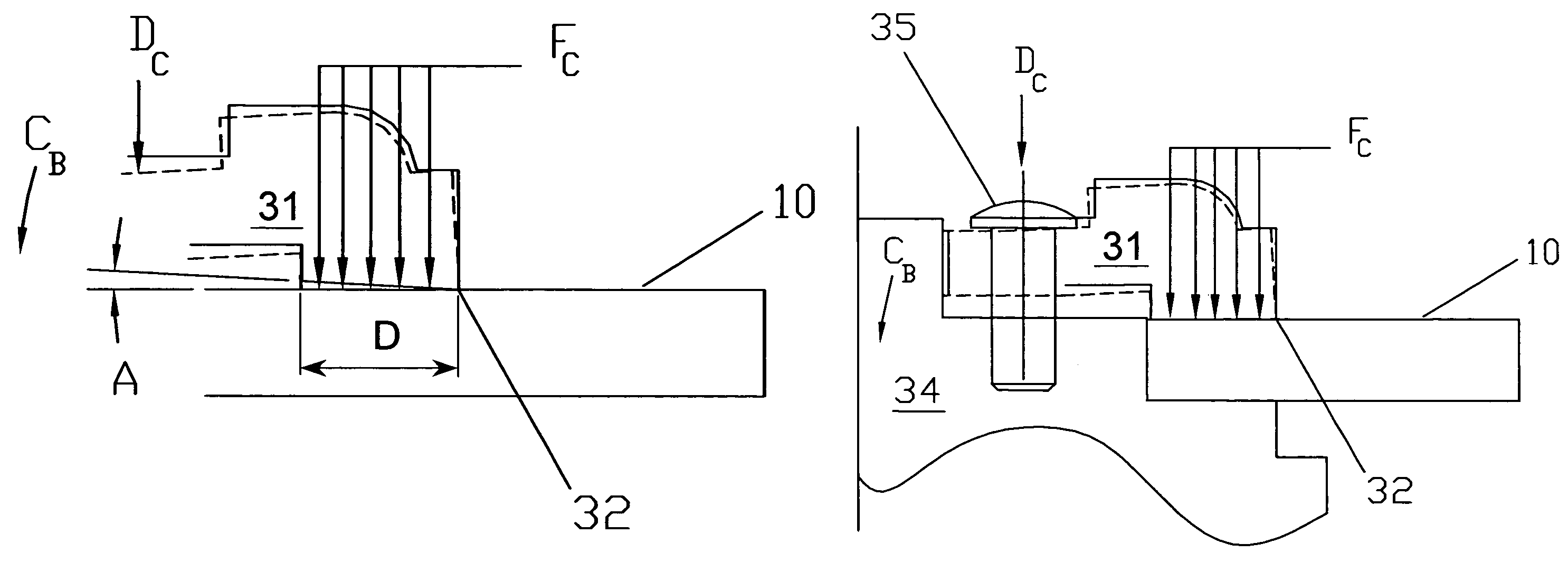
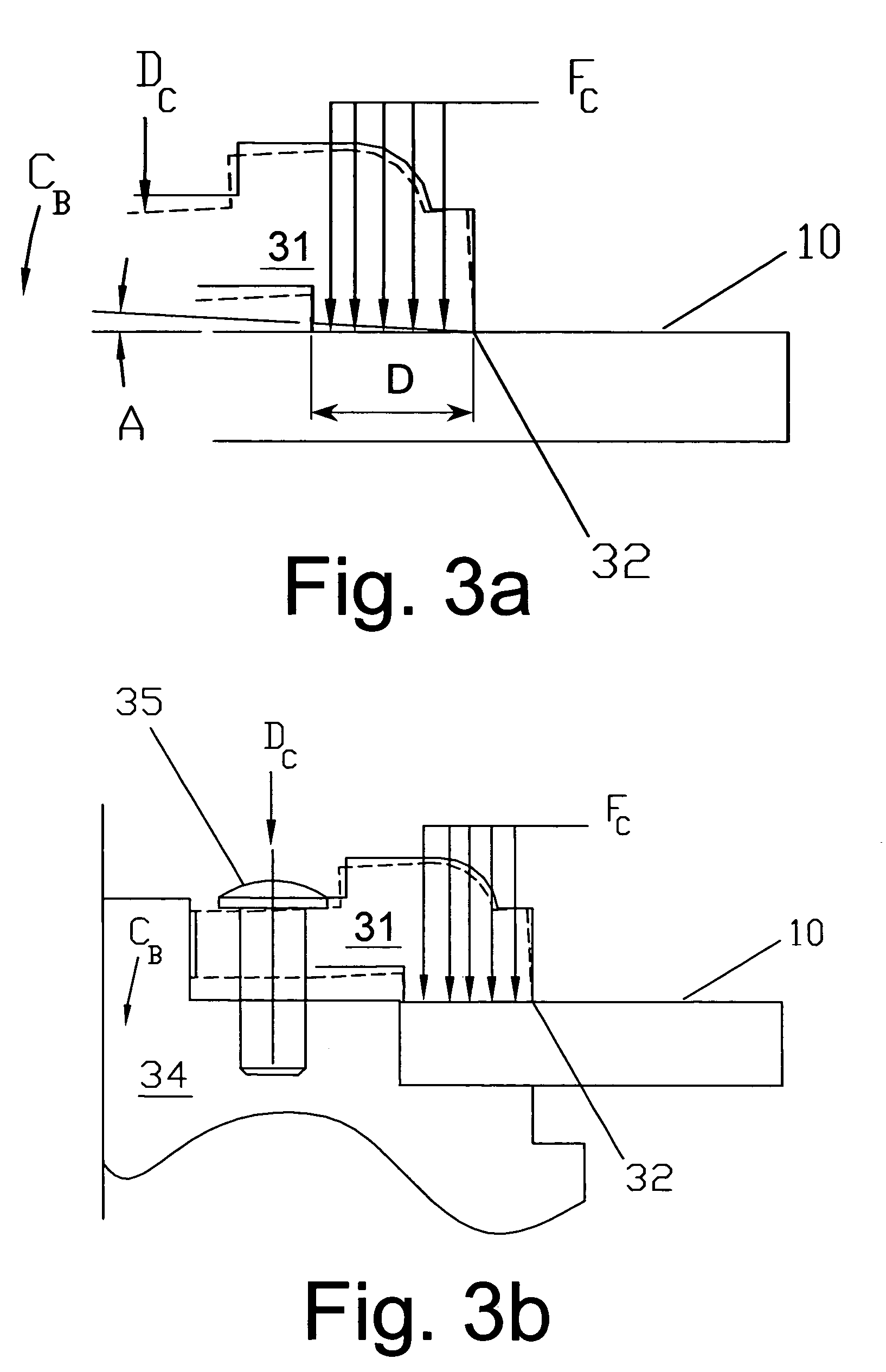
[0042]The present invention provides an offset angle disc clamp, which is an improvement in the distribution of clamp-to-disc vertical holding force. An even distribution of the vertical holding force over a set area will reduce any disc slip. This even distribution allows improved ability of the disc assembly to withstand drop force. An even distribution of vertical holding force will also decrease warping of the disc caused by the clamping mechanism itself by avoiding an annular point-contact force. Reduced warping will enhance R / W head flying height consistency (or axial run out), thus improving data transfer reliability. A reduction in head movement while reading a track (axial run out) minimizes head movement in a vertical direction with respect to the disc surface. Reduction in axial run out will improve the signal to noise ratio of the head pickup mechanism and provide for consistent signal amplitude.

[0043]The even distribution of vertical holding force is accomplished by app...


PUM


Abstract

A disc assembly in a disc drive includes a hub rotatable about a central axis. Pluralities of disc elements are mounted about outer periphery of the central axis of the hub. An annular shaped disc clamp is located about a first axial end of the hub, the annular shaped clamp holding the outermost disc to the hub by a series of equally spaced fasteners along an inner diameter of the disc clamp. The improvement therein consisting of placing an offset angle on the underside, or disc-to-hub contact area. The offset angle sloping from the inner disc contact point outward to the end of the clamp such that application of pressure during clamping will make a uniform contact area along the clamp surface as the clamp fasteners are tightened to secure the clamp to the hub. This improves flatness, axial run out, reduces repeatable run out and increases reliability.

Description

FIELD OF THE INVENTION[0001]The present invention relates generally to an apparatus and improvements in such apparatus for fastening of rotating circular plates, and, more particularly, to clamping improvements to prevent a disc from being warped due to the force associated with disc clamping.BACKGROUND OF THE INVENTION[0002]The present invention deals with disc drives. A typical disc drive includes one or more magnetic discs, which are mounted on a hub or spindle. When a plurality of discs are to be mounted on a hub, the discs are separated along the axial direction of the hub by spacers mounted between the discs. The disc, or plurality of discs, are mounted on a flange portion of the hub by a clamp apparatus. The clamping is such that the disc(s) rotate with the hub about the radial center axis of the hub. The primary method of disc clamps in prior art results in a vertical force point contact about a circumference point on the disc. This point contact can add additional warping t...

Claims


Application Information

Patent Timeline
IPC IPC(8): G11B17/022
CPCG11B17/038G11B17/0287G11B33/12
Inventor WOODS, JIM L.SODERFELT, WAYNE G.
Owner EXCELSTOR TECHNOLOGY
Why Eureka
Try Eureka