Double-protection circuit protector

a circuit protector and double protection technology, applied in the field of circuit protectors, can solve the problems of difficult, if not impossible, to ensure the springing behavior of the resilient plate, and damage caused by improper use of electricity, so as to facilitate contact, reduce melting point, and eliminate damage.

Inactive Publication Date: 2007-04-24
YU TSUNG MOU
View PDF7 Cites 18 Cited by
  • Summary
  • Abstract
  • Description
  • Claims
  • Application Information

AI Technical Summary

Benefits of technology

[0008]Thus, an objective of the present invention is to provide a circuit protector that reliably opens a circuit when the circuit is overloaded in order to protect the circuit.
[0009]Another objective of the present invention is to provide a circuit protector that eliminates damage caused by repeated opening and closing of a circuit connected to the protector.

Problems solved by technology

Due to the wide applications of electricity in the modern societies, damage caused by improper use of electricity are often observed, especially fire catastrophes caused by overheating of electrical devices.
However, the conventional circuit protector suffers several drawbacks.
For example, it is hard, if not impossible, to ensure the springing behavior of the resilient plate 21 due to manufacturing tolerance and material defects.
Further, the resilient plate 21 is not sensitive to temperature increase, which often results in significant time lag in opening a circuit when the circuit is overloaded.
It often occurs in the conventional devices that the deformation of the resilient plate is not well controlled and an incomplete disengagement is observed between the resilient plate and a terminal, which means the circuit is still in an overloaded condition and is not properly protected by the protector.
An even troublesome drawback of the conventional device is that, when the plate cools down after disengaging from an overloaded circuit, the plate may get back into contact with the circuit, leading to overloading of the circuit again, if the cause of overloading has not been removed.
Repeated engaging and disengaging of the resilient plate with the circuit definitely does no good to the circuit and the electronic / electrical appliances connected thereto and may even cause severe damage to the appliances.

Method used


Image

  • Double-protection circuit protector
  • Double-protection circuit protector
  • Double-protection circuit protector

Examples


Embodiment Construction

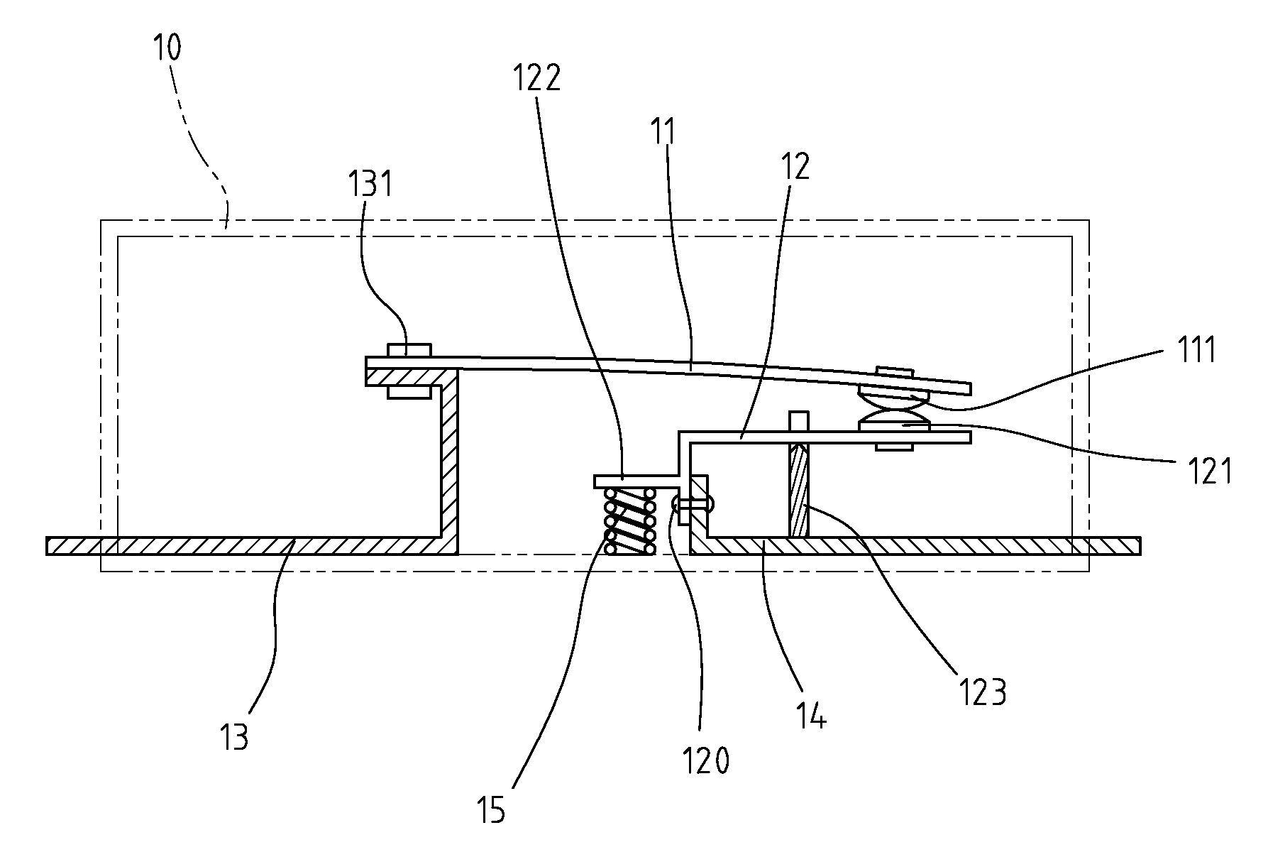
[0019]Referring to the drawings and in particular to FIG. 3, a circuit protector constructed in accordance with a first embodiment of the present invention comprises a casing 10 (shown in phantom lines) defining an interior space in which first and second conductive terminals 13, 14, which are spaced from each other and are connectable to a circuit (not shown), are fixed. A conductive member 11 made of material that can spring backward when overheated is arranged as a cantilever arm, having a proximal end fixed to the first terminal 13 by a fastener 131, such as rivet, and a free, distal end extending from the first terminal 13. A first contact 111 is formed on the free end of the first terminal 13. An example of the cantilever arm 11 is a bi-metal member having top and bottom layers made of materials of different thermal expansion rate so that when the member is heated, the member warps or deflects due to difference in expanded length between top and bottom layers.

[0020]Also referr...


PUM


Abstract

A circuit protector is connected in a circuit to protect the circuit from overloading. The circuit protector includes a casing inside which first and second terminals electrically connected to the circuit are fixed. A first cantilever member is fixed to the first terminal and has a cantilever arm that assumes a first shape in a normal condition and is convertible into a second shape in an overloading condition. A second member is supported in the casing by a pivot and has one end fixed to the second terminal by a fastener and an opposite end forming a contact engageable with the cantilever arm in the first shape and separable from the cantilever arm in the second shape. The fastener has a low melting point whereby an overloading causes the fastener to melt and break and thus allowing the second member to rotate and separating the contact from the cantilever arm. The second member is biased by a spring to facilitate separation of the contact from the second member when the fastener is broken.

Description

BACKGROUND OF THE INVENTION[0001]1. Field of the Invention[0002]The present invention relates generally to a circuit protector that functions like a circuit breaker to protect a circuit from damage caused by overloading, undesired high temperature, and in particular to a circuit protector that is triggered by high temperature caused by overloading and the likes to open the circuit.[0003]2. Prior Arts[0004]Electricity is one of the most widely used energies in modern societies. Wide applications of electricity can be found in almost all fields, especially in a computerized, information-based society. Also, household electric appliances play a more and more important role in the modern societies. Such appliances are almost powered by electricity. Due to the wide applications of electricity in the modern societies, damage caused by improper use of electricity are often observed, especially fire catastrophes caused by overheating of electrical devices.[0005]To ensure safety of using ele...

Claims


Application Information

Patent Timeline
Patent Type & Authority Patents(United States)
IPC IPC(8): H01H37/52H01H85/02
CPCH01C7/126H01H37/002H01H37/52H01H37/76
Inventor YU, TSUNG-MOU
Owner YU TSUNG MOU
Why Eureka
Try Eureka