
Quickly detachable protective cover unit of a table sawing machine

a protective cover and table sawing machine technology, applied in the direction of woodworking safety devices, metal sawing devices, manufacturing tools, etc., can solve the problems of wasting time and trouble, and achieve the effect of quick positioning, less time, and quick detachable devices

Inactive Publication Date: 2007-05-01
KINGSAND MACHINERY
View PDF28 Cites 85 Cited by
  • Summary
  • Abstract
  • Description
  • Claims
  • Application Information

AI Technical Summary

Benefits of technology

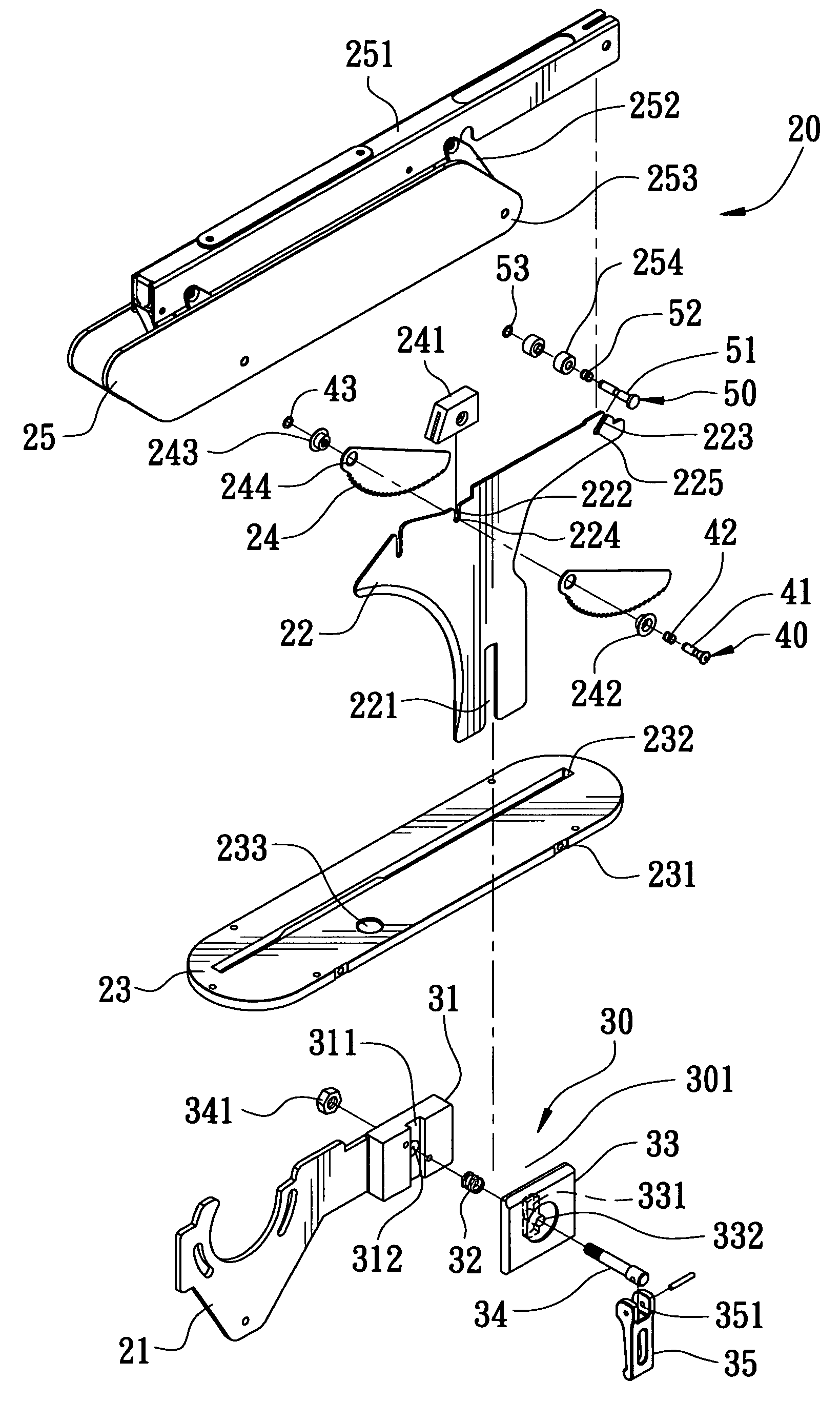
[0006]The objective of the invention is to offer the quickly detachable protective cover unit of a table sawing machine, including an extending plate connected with the saw blade of a table sawing machine. A quickly detachable handle unit is fixed at the inner end of the extending plate for quickly positioning a combining plate that is cut with two positioning notches at preset locations. A protective plate is inserted through the combining plate and then firmly positioned on the worktable of the table-sawing machine. A non-return plate and a protective cover are respectively assembled with the two positioning notches of the combining plate respectively by a quickly detachable device. By so designing, the protective cover unit can be detached from the table sawing machine with convenience and with less time as well, unnecessary to use any tool for carrying out assembling and disassembling work.

Problems solved by technology

However, to detach the conventional protective cover unit from the table sawing machine, the locking bolts of the components have to be unscrewed one by one by means of special hand tools, thus wasting much time and resulting in much trouble.

Method used


Image

  • Quickly detachable protective cover unit of a table sawing machine
  • Quickly detachable protective cover unit of a table sawing machine
  • Quickly detachable protective cover unit of a table sawing machine

Examples


Embodiment Construction

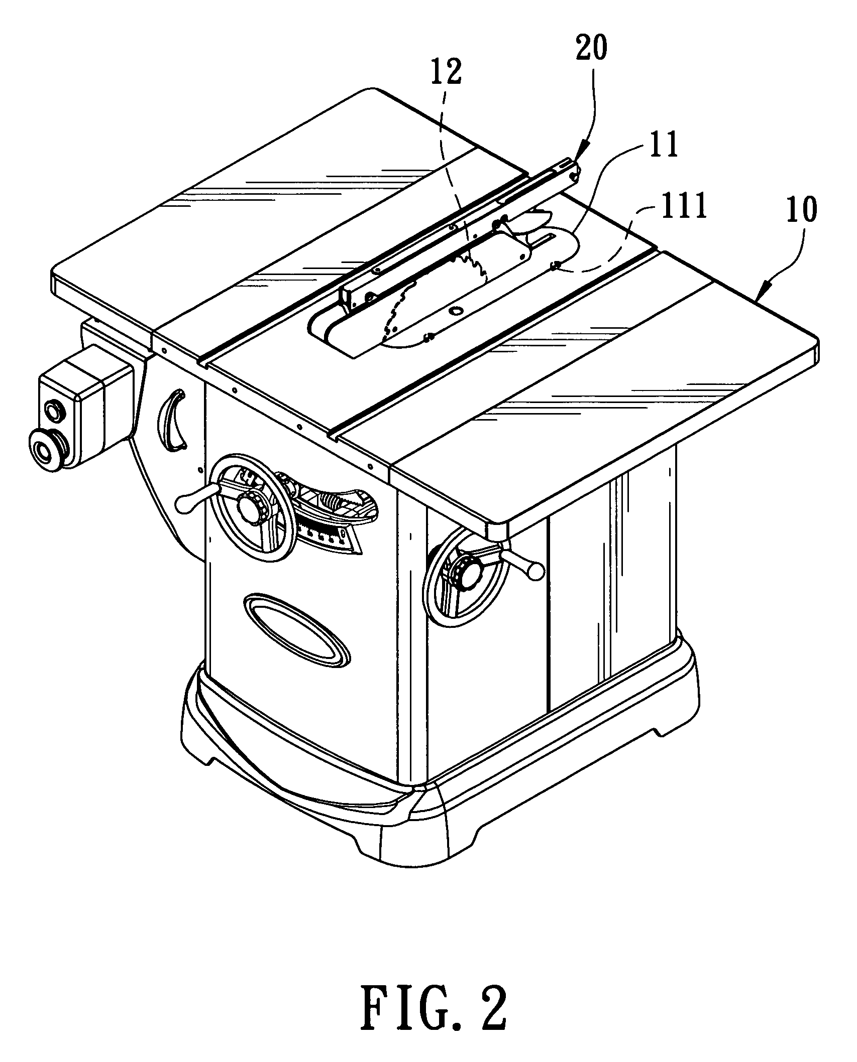
[0016]A preferred embodiment of the quickly detachable protective cover unit of a table-sawing machine in the present invention, as shown in FIGS. 2 and 3, includes a worktable 10 and a quickly detachable protective cover unit 20.

[0017]The worktable 10 of the table-sawing machine is formed at a preset location with an oval groove 11 having its lower periphery provided with protruding lugs 111 preset in number. The worktable 10 has a saw blade 12 installed in the interior.

[0018]The quickly detachable protective cover unit 20 assembled at the outer side of the saw blade 12 is composed of an extending plate 21, a combining plate 22, a protective plate 23, a non-return plate 24 and a protective cover 25.

[0019]The extending plate 21 secured at one side of the saw blade 12 has its inner end fixed with a quickly-detachable handle unit 30 composed of a fixing base 31, an elastic member 32, a position-limiting plate 33 and a quickly detachable pivot 34. The fixing base 31 is fixed on the ext...


PUM

PropertyMeasurementUnit
Shapeaaaaaaaaaa

Abstract

The quickly-detachable protective cover unit of a table sawing machine includes a protective cover, a non-return plate, a protective plate, a combining plate and an extending plate. The extending plate positioned at one side of the saw blade of a table sawing machine has its inner end fixed with a quickly-detachable handle unit for positioning the combining plate thereon. The protective plate is inserted through the saw blade and the combining plate, positioned on the table-sawing machine. The non-return plate and the protective cover are respectively provided with a quickly detachable device to fit in the positioning hole of the combining plate. The components of the quickly detachable protective cover unit are combined by quickly detachable mechanism so they can be disassembled or assembled quickly, needing no tool for carrying out disassembling work.

Description

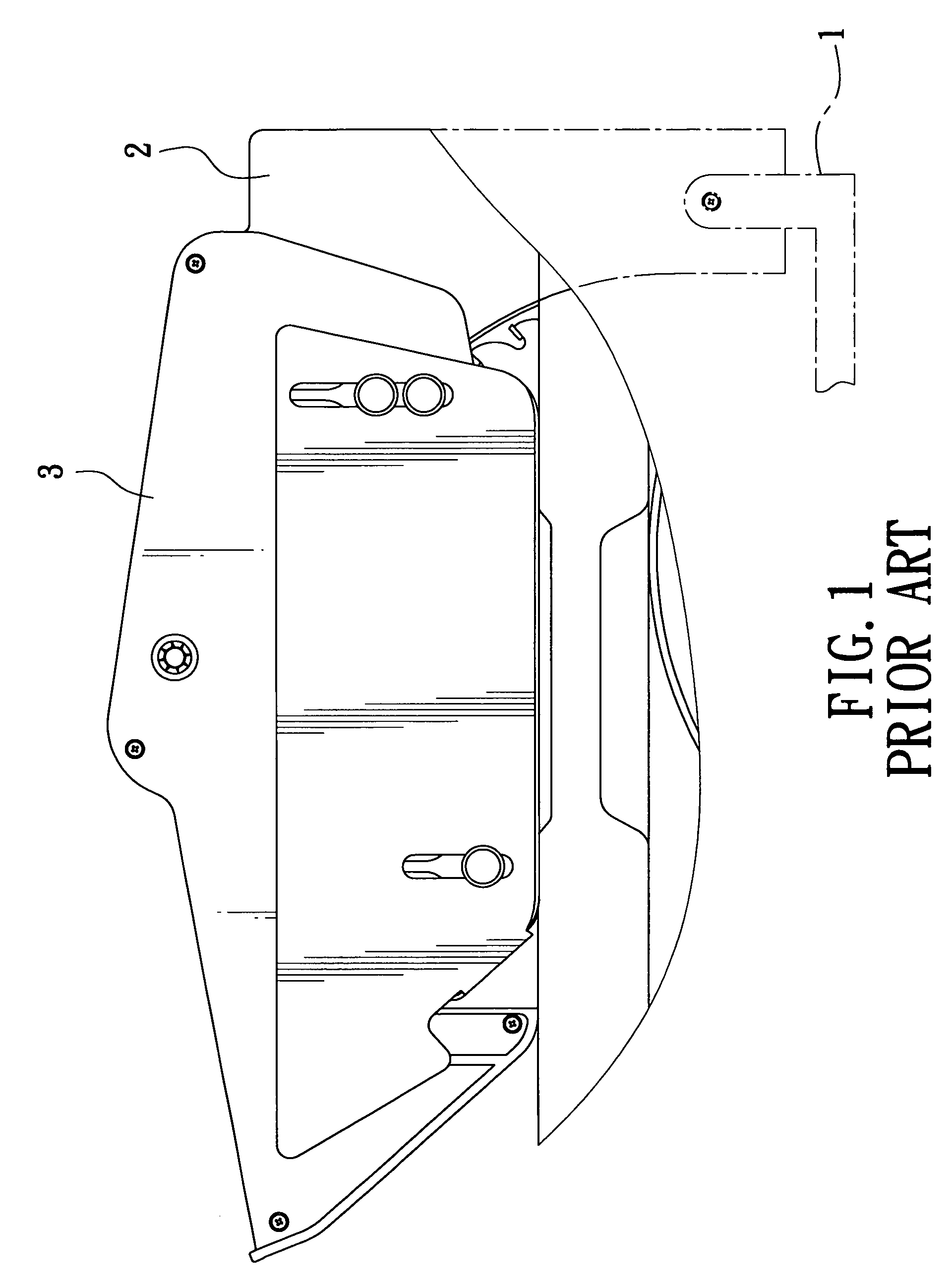
BACKGROUND OF THE INVENTION[0001]1. Field of the Invention[0002]This invention relates to a quickly detachable protective cover unit of a table-sawing machine, particularly to one able to be assembled and disassembled easily and quickly, needless to employ any tool for carrying out disassembling work.[0003]2. Description of the Prior Art[0004]Generally, a table-sawing machine is provided with a protective cover unit covered around its saw blade for the sake of protection of a user. The conventional protective cover unit of a table sawing machine, as shown in FIG. 1, includes an extending rod 1, a combining plate 2 and a protective cover 3, which are firmly combined together by bolts to prevent them from loosening or falling off.[0005]However, to detach the conventional protective cover unit from the table sawing machine, the locking bolts of the components have to be unscrewed one by one by means of special hand tools, thus wasting much time and resulting in much trouble.SUMMARY OF ...

Claims


Application Information

Patent Timeline
IPC IPC(8): B27B27/04
CPCB23D47/025B27G19/02B27G19/10Y10S83/01B27G19/08Y10T83/2077Y10T83/773Y10T83/7734
Inventor CHANG, RICHARD
Owner KINGSAND MACHINERY
Learn More