Tamper-evident quick twist closure

a fast twist and closure technology, applied in the field of closures, can solve the problems of limiting unidirectional movement, and achieve the effects of reducing material, production time and basic assembly costs, eliminating time and assembly equipment associated with threaded caps, and fast, efficient and easy removal of caps

Inactive Publication Date: 2007-05-01
MRP NEW JERSEY LLC
View PDF25 Cites 21 Cited by
  • Summary
  • Abstract
  • Description
  • Claims
  • Application Information

AI Technical Summary

Benefits of technology

[0006]The cap and tamper-evident ring are initially joined by a plurality of tapered posts extending along the side skirt, which creates open skirt areas that save material and reduce the overall production part cost. The cap is initially seated on the upper bead of the container neck, while the tamper-evident ring is initially seated on the lower bead. When the closure is opened for the first time, the tapered posts break away along a top surface of the ring, causing the ring to separate from the cap and slide down the container neck below the lower bead, which bead keeps the ring from coming off the container neck. The bottom ring being broken indicates the cap had been opened.
[0008]The one-piece closure of the present invention was developed to reduce material, production time and basic assembly cost, making it more desirable to manufacture when compared to other caps. An efficient thin cap design makes the inventive closure extremely attractive to produce. Because such design eliminates typical threads found on most containers and interior cap side walls, the cap can be pushed directly down onto the container, which eliminates the time and assembly equipment associated with threaded caps. The angles provided on both sides of the engaging and disengaging teeth that are located around the top inside skirt of the cap enable the cap to be automatically self centering left or right when the cap is assembled to the top of the container.
[0009]This design also provides a consumer with a fast, efficient and easy way to remove the cap without unthreading, squeezing or pulling. When the consumer twist's the cap left or right, the teeth become small cams and eject the cap from the container, causing the upper bead to unsnap and the cap to open. The cap is simple and easy to open but still requires a deliberate left or right turning action, which virtually eliminates the possibility of an accidental opening.

Problems solved by technology

This unidirectional movement is somewhat limiting and can be inconvenient at times. In addition, the conventional, elongated skirt portion tends to prolong the process of attaching and removing closures from containers.

Method used


Image

  • Tamper-evident quick twist closure
  • Tamper-evident quick twist closure
  • Tamper-evident quick twist closure

Examples


Embodiment Construction

[0025]The following detailed description is of the best mode or modes of the invention presently contemplated. Such description is not intended to be understood in a limiting sense, but to be an example of the invention presented solely for illustration thereof, and by reference to which in connection with the following description and the accompanying drawings one skilled in the art may be advised of the advantages and construction of the invention. In the various views of the drawings, like reference characters designate like or similar parts.

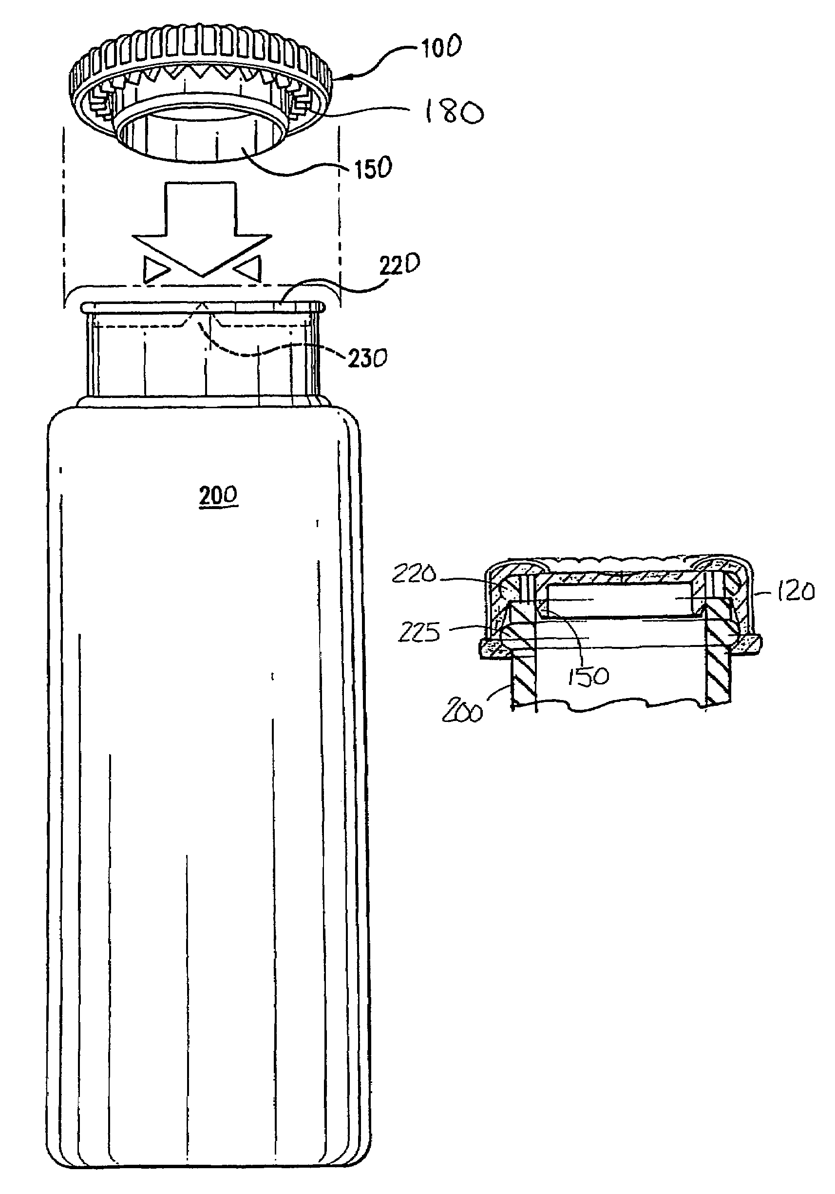
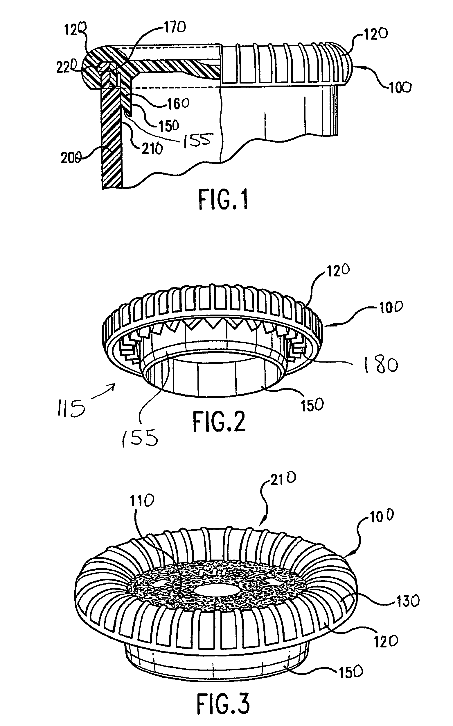
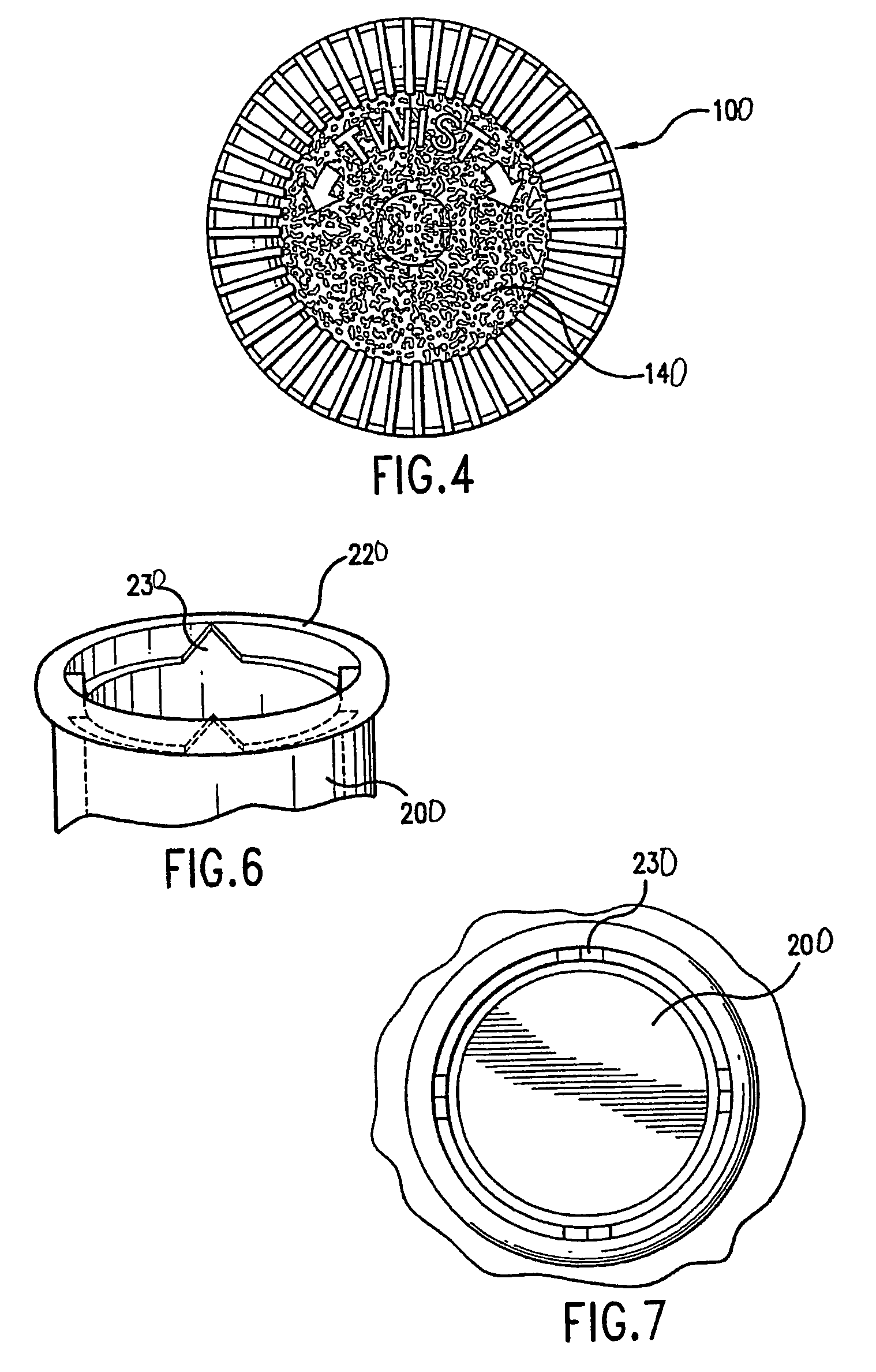
[0026]FIGS. 1–8B illustrate one embodiment of the closure of the present invention with the tamper-evident ring 300 separated from the cap 100 to illustrate aspects of the cap 100 that enable engagement and disengagement of the cap 100 with a container 200, while FIGS. 9–14 illustrate a container 200 and a cap 100 with the tamper-evident ring 300 attached thereto.

[0027]Cap 100, which is preferably injection molded as a single piece, has an ou...


PUM

PropertyMeasurementUnit
areaaaaaaaaaaa
diametersaaaaaaaaaa
side anglesaaaaaaaaaa

Abstract

A cap with a tamper-evident ring is designed to snap engage a container that is provided with an upper and lower bead. A ring of teeth provided along an inside skirt of the cap engage teeth located along an inside wall of the container. When the cap is snapped onto the container, both sets of teeth automatically engage and a plug seal provided on the cap engages the container upper bead. By turning the cap clockwise or counterclockwise, the side angles of the teeth force the cap to disengage upwards over the upper bead and unsnap from the container. When the closure is opened for the first time, the ring breaks away from the cap and slides down the container below the lower bead, which keeps the ring from coming off the container and provides evidence that the cap had been opened.

Description

[0001]This application claims priority from U.S. Provisional Application 60 / 391,349 filed Jun. 25, 2002, which is incorporated herein by reference.FIELD OF THE INVENTION[0002]The present invention is directed to closures in general, and more particularly to a one-piece injection molded cap having a tamper-evident breakaway bottom ring. After initial removal of the cap and separation of the breakaway ring, the cap can be snapped back onto the container for resealing contents contained therein.BACKGROUND OF THE INVENTION[0003]A twist closure for a container, such as a cap for a soft drink bottle having a threaded neck portion, is typically provided with a top portion and an elongated skirt portion downwardly depending therefrom that circumscribes the outer periphery of a threaded container neck. Removing the closure from the container is conventionally accomplished by rotating the closure along the threaded neck in the counterclockwise direction, while securing the closure onto the co...

Claims


Application Information

Patent Timeline
Patent Type & Authority Patents(United States)
IPC IPC(8): B65D41/47B65DB65D1/00B65D41/32
CPCB65D41/47B65D41/325
Inventor STULL, GENEAUER, ROBERT
Owner MRP NEW JERSEY LLC
Why Eureka
Try Eureka