Remote control transmitter

a transmitter and remote control technology, applied in the direction of instruments, electrical apparatus casings/cabinets/drawers, cell components, etc., can solve the problems of holder b>4/b> being liable to be lost, and achieve the effect of preventing dropping or losing the holder, facilitating battery replacement, and facilitating battery replacemen

Active Publication Date: 2007-05-01
PANASONIC CORP
View PDF9 Cites 4 Cited by
  • Summary
  • Abstract
  • Description
  • Claims
  • Application Information

AI Technical Summary

Benefits of technology

[0012]A remote-control transmitter has a holder and a casing which are respectively provided with stopping portion abutting to each other when the holder is pulled out. Due to such stopping portions, the holder is not completely detached from the casing and is stopped at the specified position. Accordingly, it is possible to obtain a remote-control transmitter which is free from dropping or losing of the holder during replacement of the battery.
[0013]Also, in the remote-control transmitter, the holder is rotatably supported in the casing. Thus, since the holder is rotatably supported in the casing, it is possible to prevent dropping or losing of the holder and to easily replace the battery.
[0014]Further, in the remote-control transmitter, an abutment on which the holder is abutted at a specified angle is provided between the holder and the casing. Thus, it is possible to keep the holder at the specified angle and to more easily replace the battery.

Problems solved by technology

Accordingly, in the above example, there arises a problem that the holder 4 might be dropped and damaged or the holder 4 is liable to be lost while looking for new battery.

Method used


Image

  • Remote control transmitter
  • Remote control transmitter
  • Remote control transmitter

Examples


first preferred embodiment

(First Preferred Embodiment)

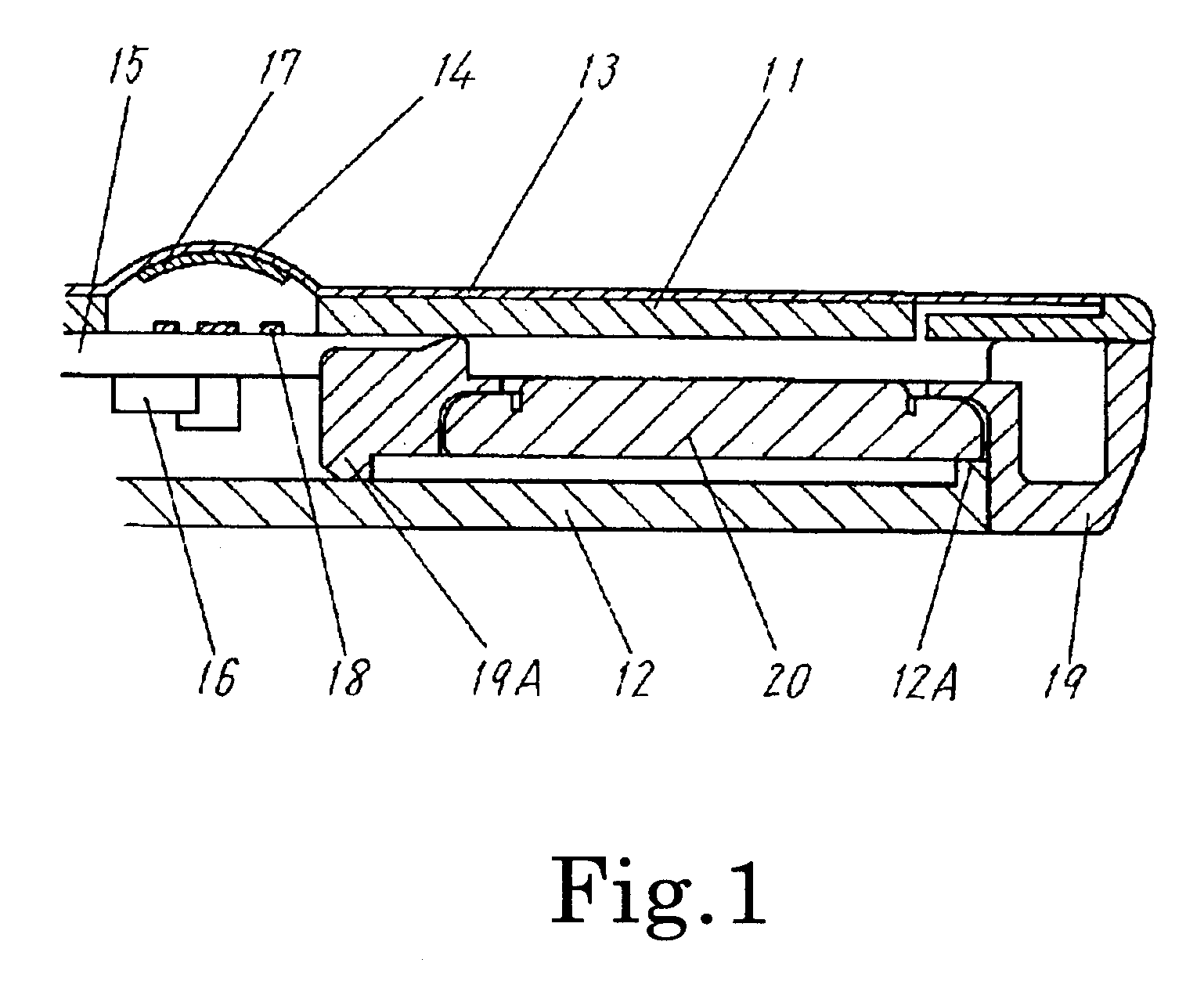
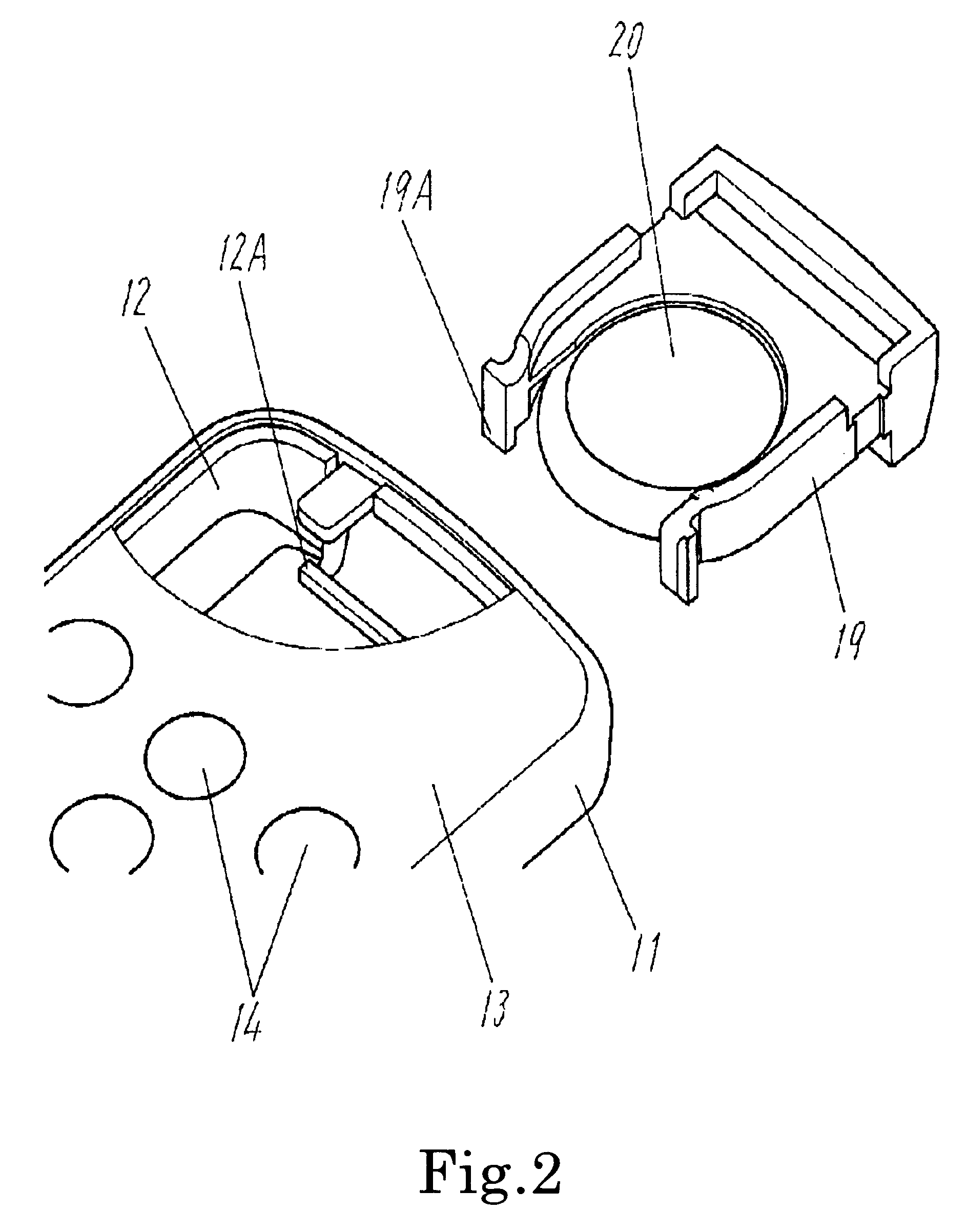
[0023]FIG. 1 is a side sectional view of a remote-control transmitter in the first preferred embodiment of the present invention. FIG. 2 is a partly sectional perspective view of the same. As shown in FIG. 1 and FIG. 2, upper casing 11 and lower casing 12 of the remote-control transmitter are integrated to form a casing. Also, panel 13 is bonded to the outer top surface of the upper casing 11. The upper casing 11 and the lower casing 12 are made of synthetic resin such as polystyrene, ABS, or the like. Also, the panel 13 is a film-like panel made of polyethylenetelephthalate or the like. The panel 13 is formed with control section 14 where a plurality of control keys are arranged. Also, each control key is protruded upward in dome-like shape.

[0024]And, in the upper casing 11 and the lower casing 12 is housed printed circuit board 15 made of paper-phenol or glass-contained epoxy with a plurality of wiring patterns (not shown) formed on the surface and unde...

second preferred embodiment

(Second Preferred Embodiment)

[0034]The second preferred embodiment of the present invention will be described in the following.

[0035]In the remote-control transmitter in the second preferred embodiment of the present invention, same as in the first preferred embodiment shown in FIG. 1, upper casing 11 is formed with control section 14 where a plurality of control keys are arranged. Also, on printed circuit board 15 housed in the upper casing 11 and lower casing 12 is formed circuit 16 which generates and transmits remote-control signals for remote control of apparatuses.

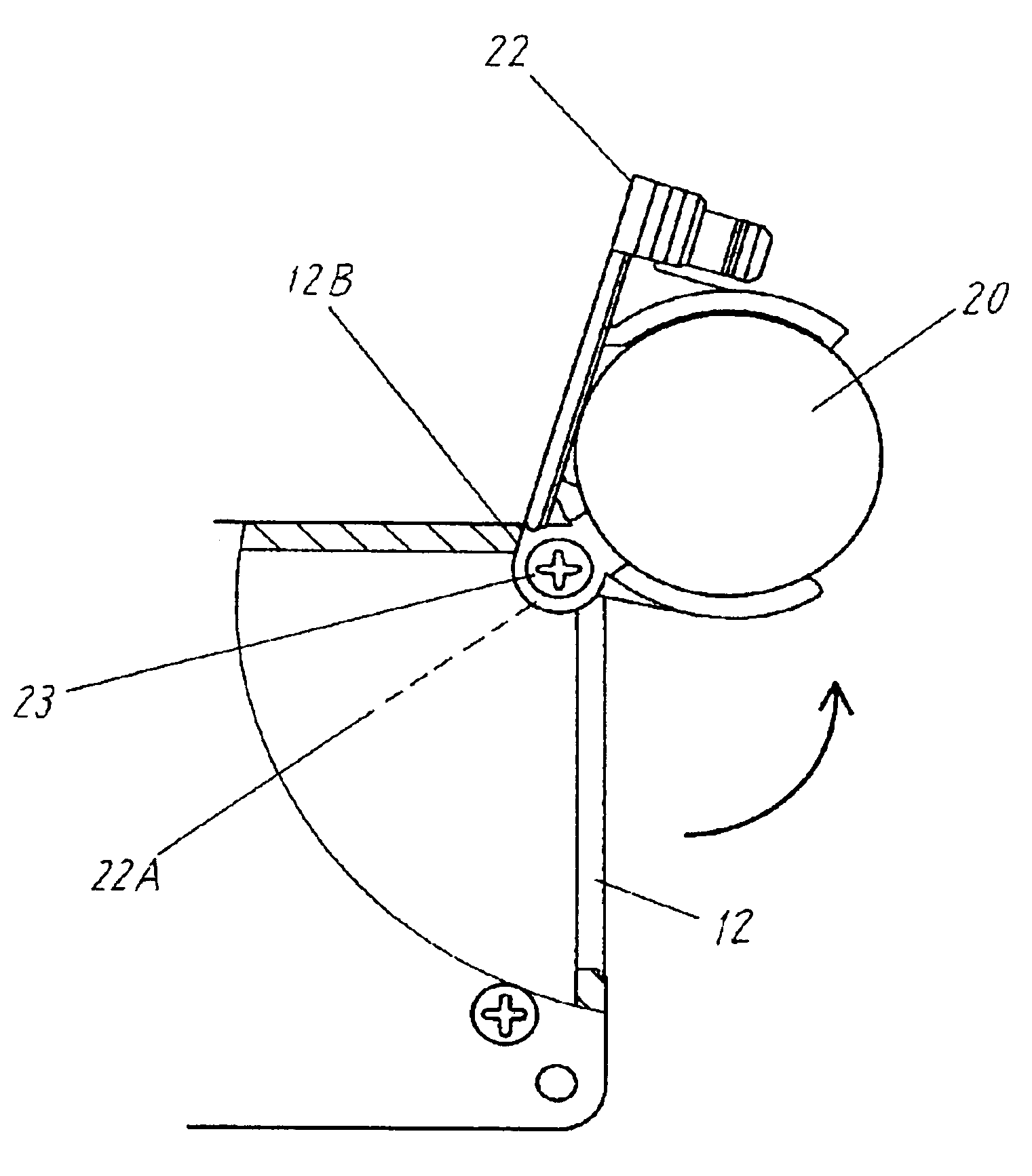
[0036]FIG. 5 is a partly plane sectional view as viewed from the rear side of the remote-control transmitter in the second preferred embodiment of the present invention. In FIG. 5, disk-like button battery 20 loaded in holder 22 made of synthetic resin comes in contact with an electrode (not shown) disposed on the printed circuit board 15 and is electrically connected to circuit 16.

[0037]Further, as shown in FIG. 5, ...


PUM

PropertyMeasurementUnit
angleaaaaaaaaaa
sizeaaaaaaaaaa
weightaaaaaaaaaa

Abstract

A control section with control keys arranged therein is formed, and upper and lower casings for storing a circuit, and holder capable of loading a button battery and sliding within said casing are respectively provided with stopping portion abutting each other when the holder is pulled out, and thereby, it is possible to obtain a remote-control transmitter which is free from dropping or losing of the holder.

Description

BACKGROUND OF THE INVENTION[0001]1. Field of the Invention[0002]The present invention relates to a remote-control transmitter used for remote control of various electronic apparatuses such as TV, video, and air conditioners.[0003]2. Description of the Related Art[0004]Recently, various electronic apparatuses such as TV, video, and air conditioners have been increasingly reduced in size and weight. And, in remote-control transmitters for remotely controlling these apparatuses, card types reduced in thickness and weight are widely used. Many of such remote-control transmitters employ disk-like button battery and are reduced in thickness and weight.[0005]Such a conventional remote-control transmitter will be described with reference to FIG. 7.[0006]FIG. 7 is a perspective view of a conventional remote-control transmitter. In FIG. 7, control section 2 with a plurality of control keys arranged therein is formed on the surface of casing 1 made of synthetic resin. Also, each control key is...

Claims


Application Information

Patent Timeline
Patent Type & Authority Patents(United States)
IPC IPC(8): G08C19/12H01H9/02H01M2/02H01M2/10H04Q9/00
CPCH01H9/0235H01M2/1055H01M2/0222H01H2239/058Y02E60/10H01M50/109H01M50/213
Inventor NAKAMURA, TAKAYA
Owner PANASONIC CORP
Why Eureka
Try Eureka