Automated system and method for tool mark analysis

a tool mark and automatic system technology, applied in the field of automatic acquisition and comparison of tool mark data, can solve the problems of tool mark examiners being unable to quantify their level of certainty or the probability of making an error-prone conclusion, and mark may present many depth or elevational variances

Active Publication Date: 2007-05-01
INTELLIGENT AUTOMATION LLC
View PDF35 Cites 52 Cited by
  • Summary
  • Abstract
  • Description
  • Claims
  • Application Information

AI Technical Summary

Problems solved by technology

An individual tool mark may present many depth or elevational variances, and these variances are often microscopic so as to be indetectable with the naked eye.
Currently these tool mark-to-tool mark comparisons are made manually by the tool marks examiner visually inspecting pairs of tool marks under a comparison microscope, making forensic tool mark examination a very time consuming process.
Even if certain of a particular conclusion, however, the tool marks examiner is generally unable to quantify his or her level of certainty or the probability of making an erroneous conclusion.
The foregoing limitations of current tool mark evaluation are particularly disadvantageous in view of the raised expectations for quantitative precision in forensic analysis resulting from the development of DNA identification techniques and the high level of accuracy achievable in the establishment of error rates associated with DNA identification.
One problem of 2D data acquisition is that the transformation relating light incident on the specimen's surface and light reflected by the specimen's surface depends not only on the surface features but also on numerous independent parameters including the incident light angle, the camera angle, variations in the reflectivity of the specimen's surface, light intensity and accurate specimen orientation.
Existing 2D-based analysis and comparison systems ordinarily do not compensate for the effects of these parameters on the acquired 2D data.
Another problem of 2D data acquisition relates to the phenomenon of “shadowing” resulting from smaller surface features being “shadowed” by larger surface features for a given incident light angle.
Arbitrarily small changes in the incident light angle may determine whether certain surface features are detected or not, and a similar problem applies to the angle of view of the camera.

Method used


Image

  • Automated system and method for tool mark analysis
  • Automated system and method for tool mark analysis
  • Automated system and method for tool mark analysis

Examples


Embodiment Construction

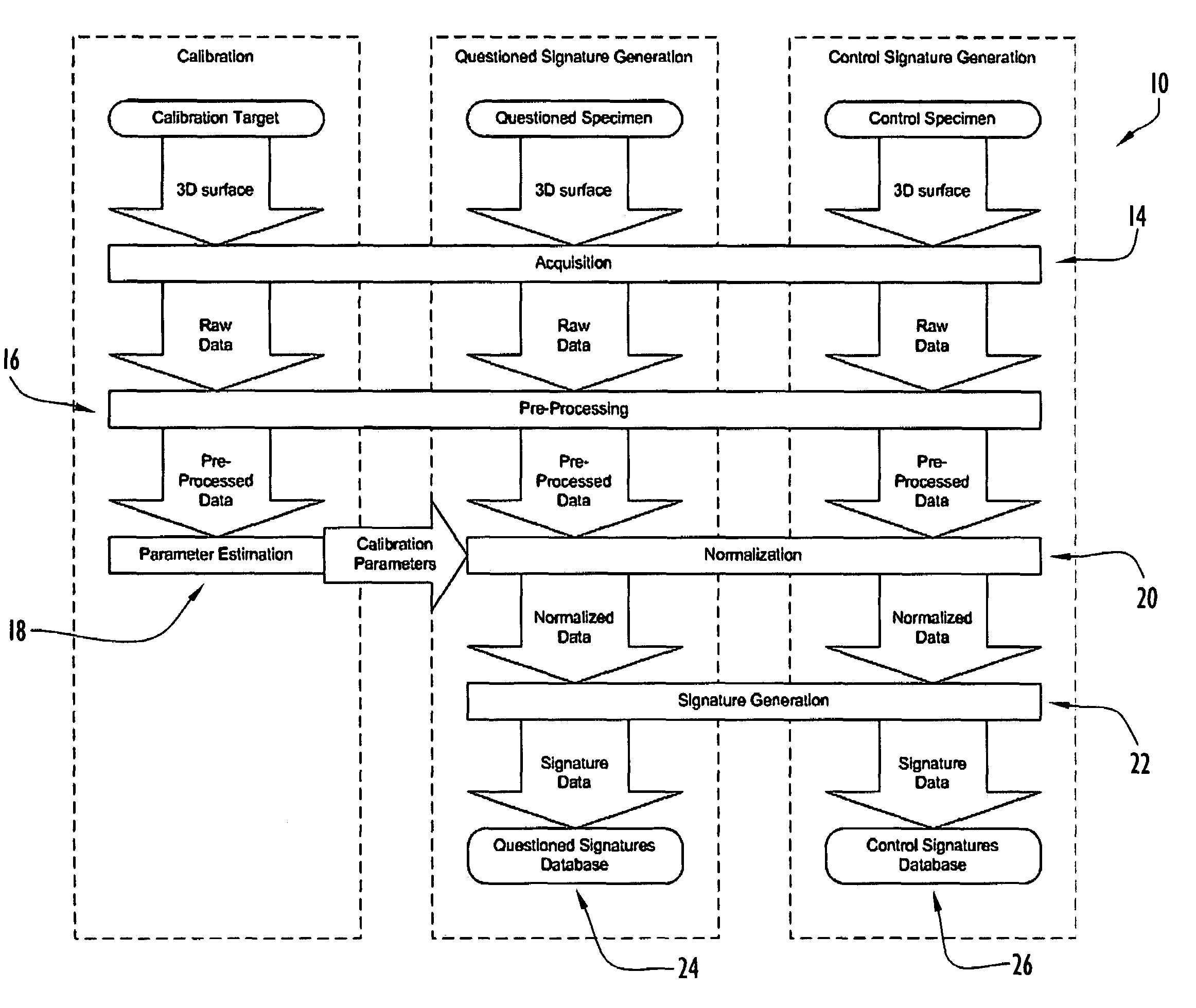
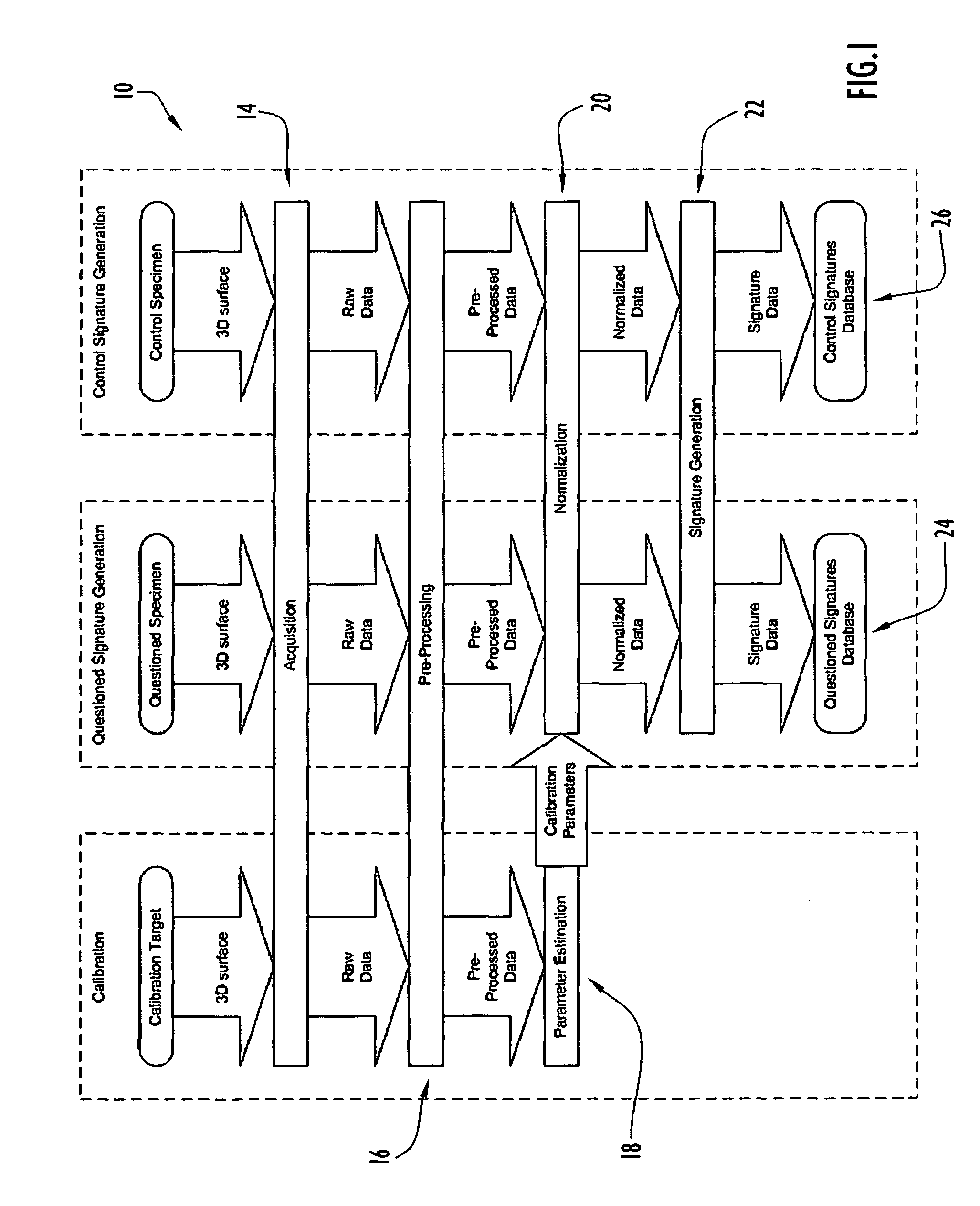
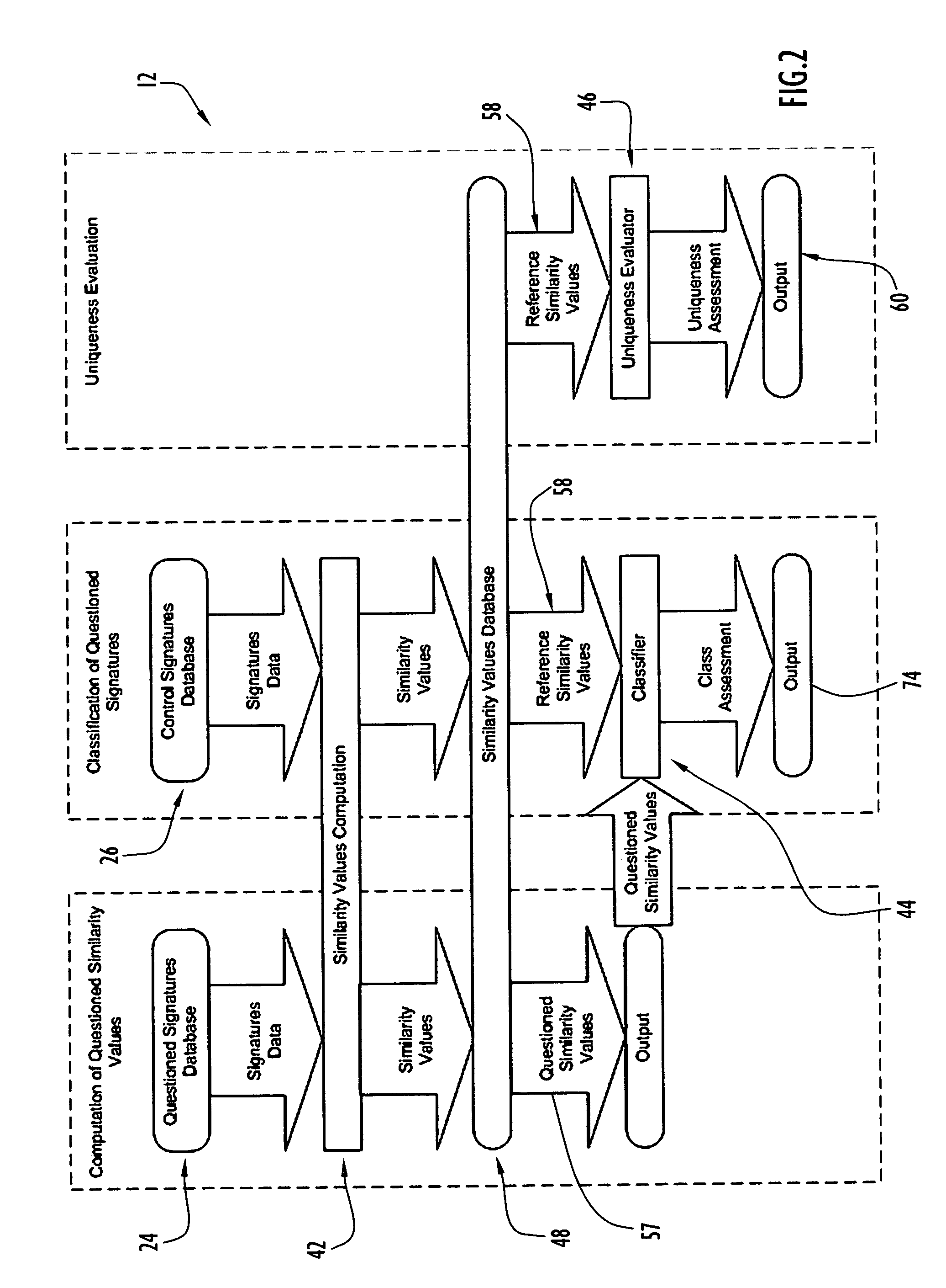
[0064]The automated system for tool mark analysis and the method for tool mark analysis described herein are designed to perform automated acquisition and comparison of tool mark data using 3D information in an objective, unbiased manner. The automated system and method for tool mark analysis involves the characterization of tool marks as 3D objects and the use of statistical methodologies applied to a well-defined similarity metric to quantify the statistical difference between known matching and known non-matching tool marks. The automated system and method for tool mark analysis are capable of providing a numerical value reflecting the degree of similarity between two tool marks under comparison, a statistically-based assessment of the likelihood that a particular tool created a pair of tool marks under consideration, and / or an assessment of the uniqueness of the tool marks of a particular class. Various features of the system and method for tool mark analysis involve high level ...


PUM


Abstract

An automated system for tool mark analysis includes an acquisition mechanism for acquiring 3D data of tool marks left on the surfaces of specimens by tools, a signature generation module for generating tool mark signatures from the acquired data, an analysis unit for comparing pairs of the tool mark signatures to obtain a numerical similarity value reflective of their similarity, and a database in which the similarity values are stored. An automated method for tool mark analysis involves the steps of acquiring the 3D data of tool marks, generating the tool mark signature, statistically evaluating pairs of the tool mark signatures, and providing a numerical similarity value for each pair of tool mark signatures reflecting the degree of similarity between the tool mark signatures of each pair. The method is carried out with automated assistance of a computer.

Description

CROSS-REFERENCE TO RELATED PATENT APPLICATION[0001]This application claims priority from prior provisional patent application Ser. No. 60 / 605,998 filed Aug. 31, 2004, the entire disclosure of which is incorporated herein by reference.BACKGROUND OF THE INVENTION[0002]1. Field of the Invention[0003]The present invention relates generally to automated tool mark analysis and, more particularly, to the automated acquisition and comparison of tool mark data using three-dimensional information.[0004]2. Brief Discussion of the Related Art[0005]Objects that are acted or operated on by tools are normally left with tool marks as a result of being acted or operated on by the tools. Many types of commonly used mechanical tools, such as screw drivers, pliers, bolt cutters, crimping tools, hammers and other mechanical tools, impart tool marks to the objects they are used on. Tool marks generally comprise regions where the surfaces of the objects have been deformed or altered because microscopic im...

Claims


Application Information

Patent Timeline
Patent Type & Authority Patents(United States)
IPC IPC(8): G06F11/30
CPCF42B35/00G06T7/0004G06T2200/04G06T2207/10028G06T2207/10056G06T2207/30136
Inventor BACHRACH, BENJAMIN
Owner INTELLIGENT AUTOMATION LLC
Why Eureka
Try Eureka