
Vehicle steering wheel

a steering wheel and vehicle technology, applied in the direction of steering control, mechanical control device, controlling member, etc., can solve the problems of vibration of the steering wheel, long journeys exhausting for the driver, and impair the steering sensation, etc., to achieve the effect of simple and cheap production

Inactive Publication Date: 2007-05-08
TRW AUTOMOTIVE SAFETY SYST
View PDF23 Cites 7 Cited by
  • Summary
  • Abstract
  • Description
  • Claims
  • Application Information

AI Technical Summary

Benefits of technology

[0005]The vibration-decoupling means is formed by an elastic bearing, as provided by the preferred embodiment, the bearing being, for example, a composite bearing. It consists of several parts, some of which are so elastic that they do not transfer vibrations, which occur for example in the region of the steering wheel hub or the steering shaft, to the steering wheel rim. An immediate contact between adjacent rigid parts of the steering wheel in the region of the vibration-decoupling means is avoided as the forces in all directions are transferred via the elastic bearing.
[0006]The spoke and / or the steering wheel rim can have a foam casing which is part of the bearing, so that the bearing can be constructed at a favorable cost and is produced at least partially during the process of encasing with foam.
[0009]Another possibility of connection of the parts separated from each other by the vibration-decoupling means consists in dividing the spoke into spoke sections which overlap to create a fastening flange. For example, the vibration-decoupling means can be provided in the region of the fastening flange. Furthermore, the spoke sections can also make possible the introduction of the pin into the receiving shell, because usually the steering wheel rim is undivided, so that a radial joining of radial inner sections of the steering wheel into radially outer sections is only possible with increased structural expenditure.
[0011]The connecting of the spoke with the steering wheel rim, which is as far as possible undivided, can take place for example in that the steering wheel rim is equipped with a skeleton ring having radially inwardly protruding projections of sheet metal which projections are bent such that they engage an end of the spoke facing the skeleton ring. This type of fastening is very simple and cheap to produce.

Problems solved by technology

During driving, vibrations of the steering wheel can occur, which makes long journeys exhausting for the driver and impairs the steering sensation.

Method used


Image

  • Vehicle steering wheel
  • Vehicle steering wheel
  • Vehicle steering wheel

Examples


Embodiment Construction

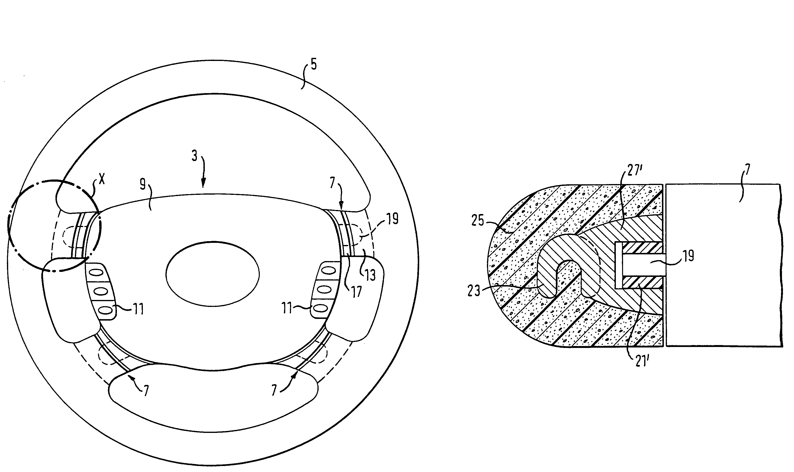
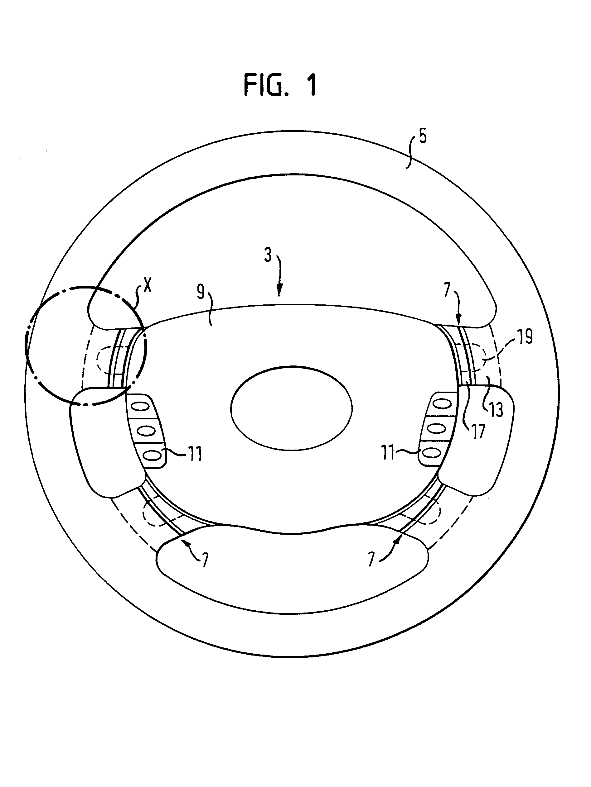
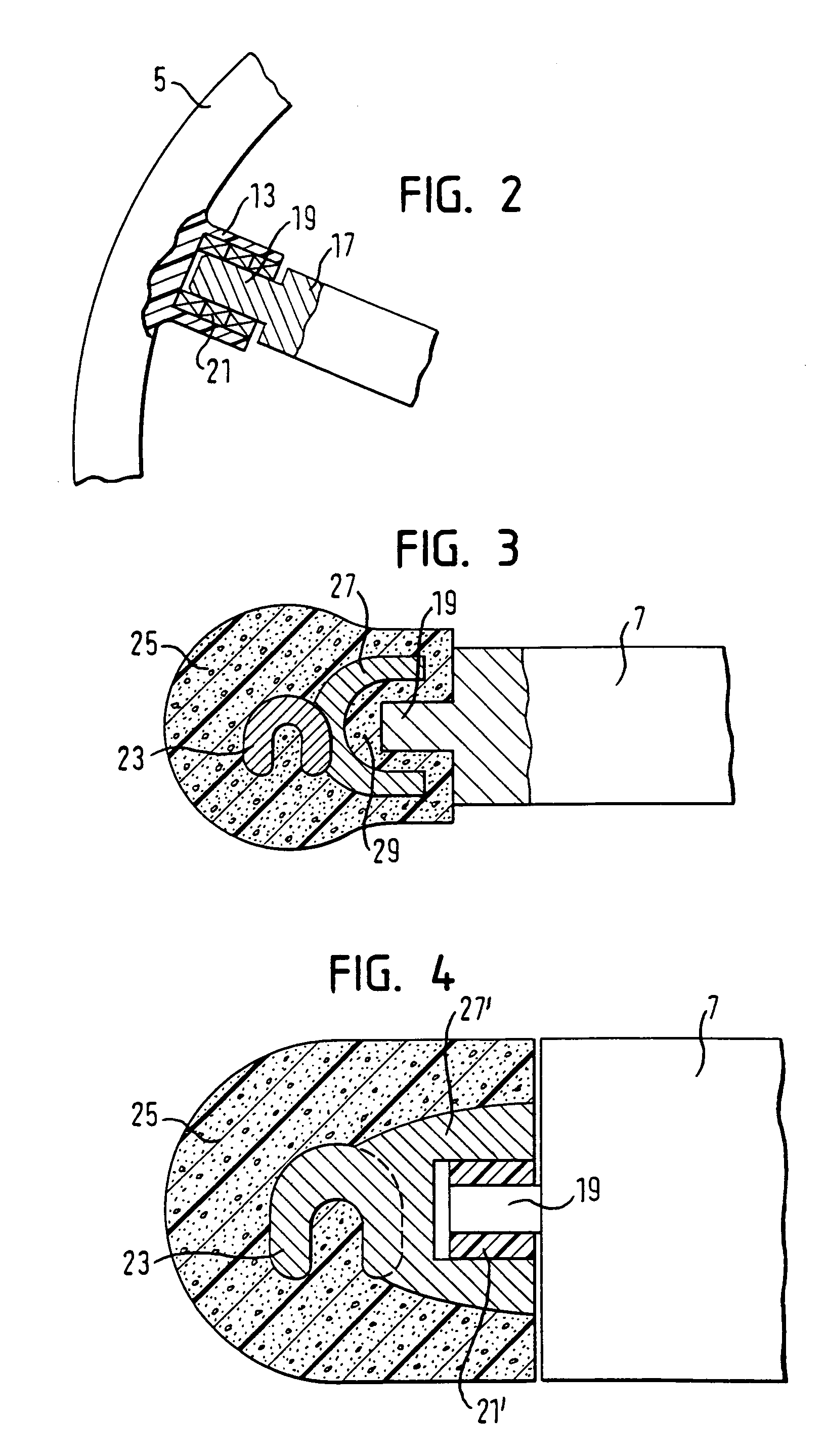
[0022]In FIG. 1 a vehicle steering wheel is illustrated, which has a hub 3, a steering wheel rim 5 and four spokes 7. A horn switch area is designated by 9 and multifunction switches are designated by 11. Each spoke 7 is divided into an outer and a radially inner spoke section 13 and 17, respectively, in order to largely isolate the steering wheel rim 5 relative to the hub 3 with regard to vibrations. For this, in each spoke 7 an vibration-decoupling means is provided in the region of the transition point of the spoke sections 13, 17, which can be better seen in FIG. 2. The inner spoke section 17 has a pin 19, which is inserted into a composite bearing 21, which sits in an opening in the outer spoke section 13. The composite bearing 21 is composed of several elastic rings which achieve an isolation of vibrations of the steering wheel rim 5 with outer spoke section 13 fastened thereto from the inner spoke section 17 together with hub 3. The vibration-decoupling means acts in all dire...


PUM


Abstract

The invention relates to a vehicle steering wheel comprising a hub, a steering wheel rim, and at least one spoke having at least one spoke section. An vibration-decoupling means is provided on the spoke which acts in all directions and at least largely isolates the steering wheel rim in terms of vibrations from the at least one section of the spoke.

Description

TECHNICAL FIELD [0001]The invention relates to a vehicle steering wheel.BACKGROUND OF THE INVENTION [0002]During driving, vibrations of the steering wheel can occur, which makes long journeys exhausting for the driver and impairs the steering sensation. Therefore, endeavors are being made to dampen the steering wheel with respect to the steering shaft or, for example, to fasten the gas bag module in an oscillating manner in the steering wheel hub.[0003]From DE 20 13 795 B2, for example, there is known a steering wheel which has a steering wheel hub, a steering wheel rim and two spokes consisting of spoke sections. Ball joints including damping elements are each provided between the spoke sections themselves, as well as at the transition points of the spoke to the steering wheel rim and to the steering wheel hub, respectively. The spoke structure disclosed here must have a specific rigidity, so that one can not start out from an isolation of vibrations in a radial and / or circumferent...

Claims


Application Information

Patent Timeline
Patent Type & Authority Patents(United States)
IPC IPC(8): B62D1/04B62D1/08B62D7/22
CPCB62D1/08B62D7/222Y10T74/20834
Inventor LORENZ, CHRISTIAN
Owner TRW AUTOMOTIVE SAFETY SYST
Learn More