
Throttle body with hydrocarbon adsorber

a technology of hydrocarbon adsorber and throttle body, which is applied in the direction of machines/engines, combustion-air/fuel-air treatment, and separation processes, etc., can solve the problems of difficult and expensive achieving a complete sealed manifold, contributing to the formation of smog, and affecting the desirable option. , to achieve the effect of increasing the probability

Inactive Publication Date: 2007-05-08
DELPHI TECH INC
View PDF21 Cites 26 Cited by
  • Summary
  • Abstract
  • Description
  • Claims
  • Application Information

AI Technical Summary

Benefits of technology

The invention is a system that includes a carbon adsorber element in an internal combustion engine's throttle body. The element can be installed in the throttle body's wall or on the surface of the throttle blade. When the engine is shut down, the throttle valve remains slightly open, allowing any HC emissions to pass through and be adsorbed by the carbon adsorber. This system improves the adsorption of HC emissions and reduces emissions in the engine.

Problems solved by technology

Gasoline-fueled motor vehicles have many sites from which hydrocarbons (HC) may evaporate into the environment, thereby contributing to the formation of smog.
Employing an engine's electronic throttle control to close the intake at shut down may impair the desirable option of a so-called “limp home” mode in which a vehicle may be driven in event of a partial failure of the engine electronics control system.
In these systems, achieving a completely sealed manifold is difficult and expensive.
Adsorptive grids in the intake air flow path are undesirable as they are expensive to fabricate, brittle and therefore vulnerable to breakage, and inherently restrict the volume of intake air.
Carbon sheeting applied to inner surfaces of the manifold and air ducts is only partially successful because much HC laden air can escape the manifold without being brought into proximity with an adsorptive surface.

Method used


Image

  • Throttle body with hydrocarbon adsorber
  • Throttle body with hydrocarbon adsorber
  • Throttle body with hydrocarbon adsorber

Examples


Embodiment Construction

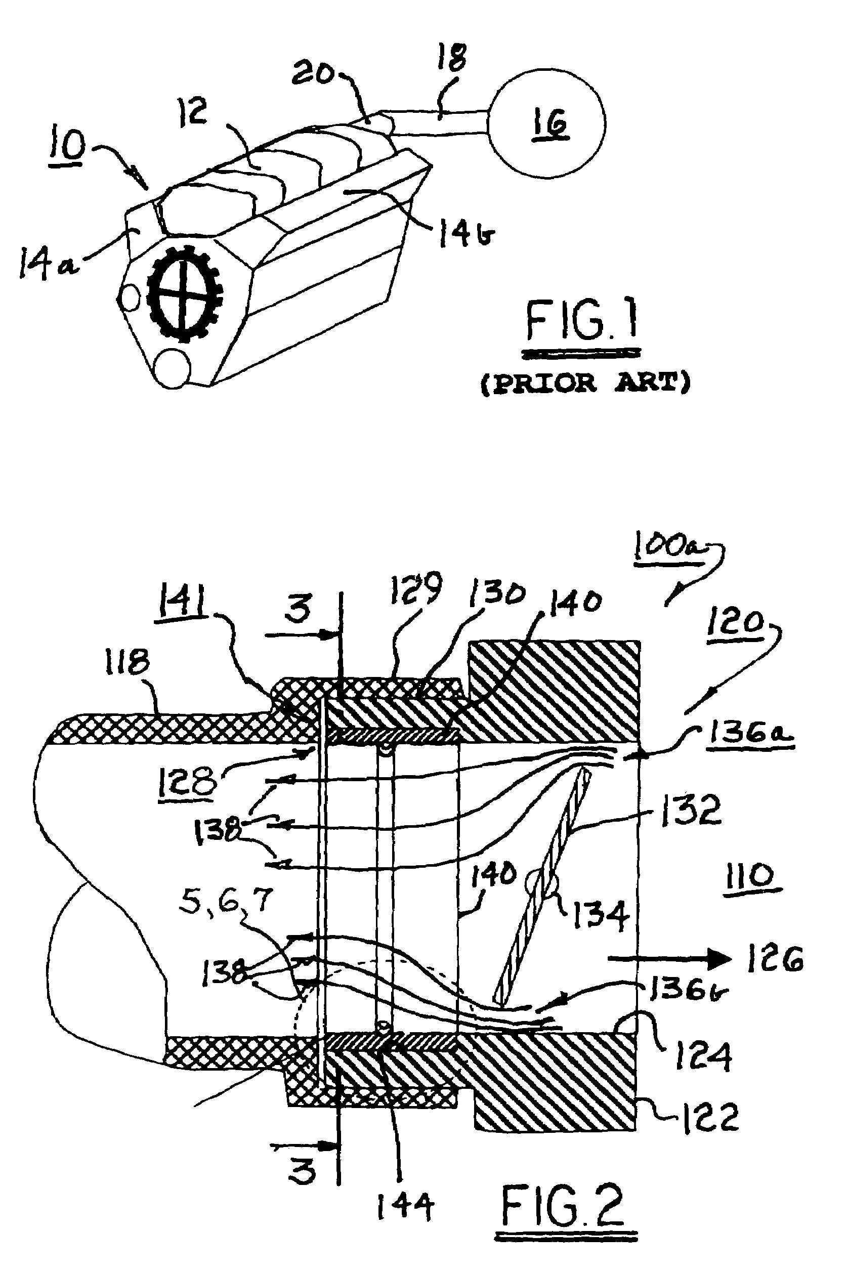
[0017]Referring to FIG. 1, a prior art V-style internal combustion engine 10 includes an intake manifold 12 for distributing air in known fashion to first and second engine heads 14a,14b. Air is drawn into engine 10 through an entrance air cleaner 16 and supply duct 18. An air intake throttle valve assembly 20 regulates the flow rate of air into the engine. In a default or engine shutdown position, throttle valve assembly 20 is nearly closed.

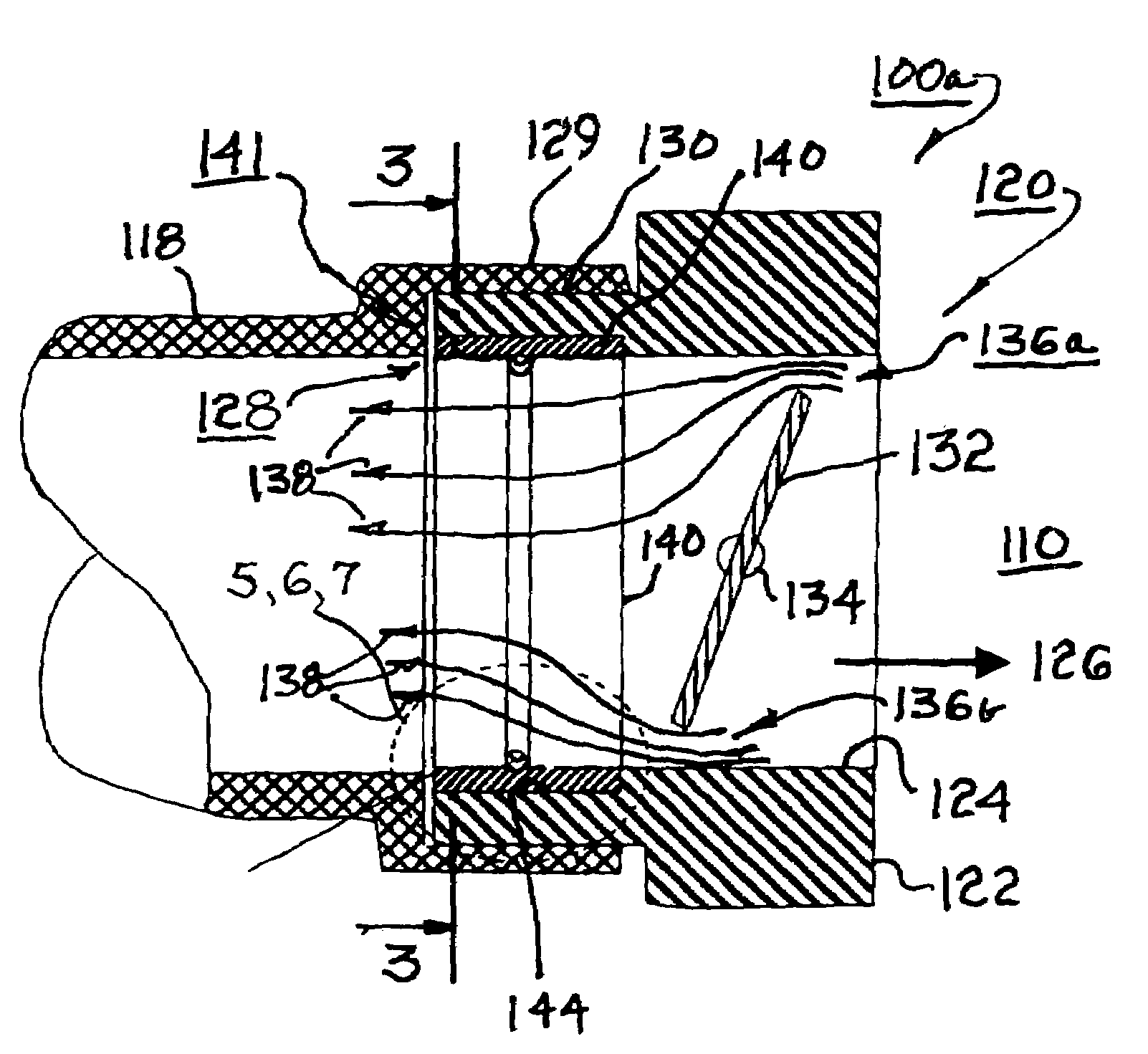
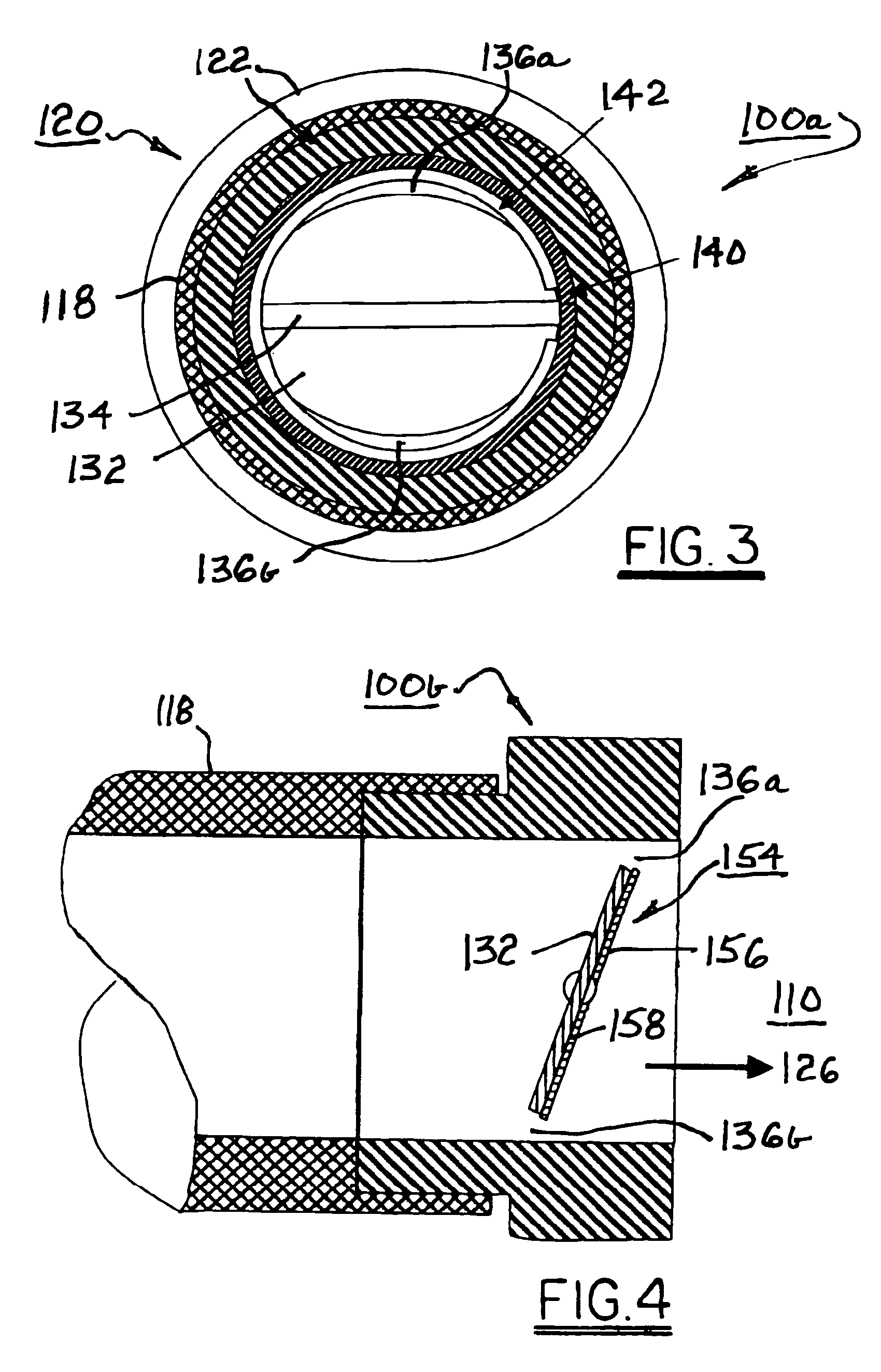
[0018]Referring to FIGS. 2 and 3, a hydrocarbon adsorption system 100a, 100b in accordance with the invention comprises a throttle valve assembly provided with hydrocarbon adsorption means as described in detail below.

[0019]A throttle valve assembly 120 comprises a valve body 122 having a generally cylindrical bore or throat 124 extending through body 122 for admission of intake air 126 to an internal combustion engine 110. Preferably, air supply duct 118 is provided with an inner diameter similar to the diameter of throat 124 to provide a smoot...


PUM

PropertyMeasurementUnit
volumeaaaaaaaaaa
areasaaaaaaaaaa
flow rateaaaaaaaaaa

Abstract

A hydrocarbon adsorber system in accordance with the invention comprising a carbon adsorber element installed in a throttle body of an internal combustion engine. The element may be installed on a wall or in a groove in the wall of the throttle throat at a location immediately upstream (outside) the throttle blade in the air flow direction, and / or an element may be installed on the downstream surface of the throttle blade itself. When an engine is shut down, the engine throttle normally remains slightly open. Any hydrocarbon emissions must pass through this slight opening, and applying carbon adsorbers to these locations takes advantage of proximity to such an opening, as any hydrocarbon emissions must pass close by the carbon adsorbers and thus have a much-increased probability of being adsorbed, in comparison with prior art more general carbon adsorption sites.

Description

TECHNICAL FIELD[0001]The present invention relates to internal combustion engines; more particularly, to devices for controlling hydrocarbon emissions from internal combustion engines; and most particularly, to adsorptive apparatus for preventing hydrocarbon leakage from the intake manifold of an internal combustion engine after engine shutdown.BACKGROUND OF THE INVENTION[0002]Gasoline-fueled motor vehicles have many sites from which hydrocarbons (HC) may evaporate into the environment, thereby contributing to the formation of smog. One such known site is the intake manifold of a carbureted or port-injected internal combustion engine. As HC emission regulations are tightened, a means is needed to prevent residual HC vapor from escaping from the intake manifold through the throttle valve assembly after engine shutdown. Known approaches have included, among others, closing off the intake and idle air with the throttle valve when the engine is shut off; adding adsorptive carbon grids i...

Claims


Application Information

Patent Timeline
Patent Type & Authority Patents(United States)
IPC IPC(8): F02M37/20F02M33/02
CPCB01D53/0446F02M35/02F02M35/10019F02M35/10144F02M35/10255B01D53/0431B01D2253/102B01D2257/702B01D2259/4566F02M25/08
Inventor BURKE, DAVID H.IANNONE, CHARLES A.
Owner DELPHI TECH INC
Learn More