Washpipe seal

a technology for washing pipes and seals, applied in the direction of drilling pipes, mechanical equipment, borehole/well accessories, etc., can solve the problems of unsatisfactory solutions and extremely difficult removal of them, and achieve the effects of easy removal and replacement, low difficulty, and easy radial removal

Inactive Publication Date: 2007-05-08
SKF USA INC
View PDF21 Cites 28 Cited by
  • Summary
  • Abstract
  • Description
  • Claims
  • Application Information

AI Technical Summary

Benefits of technology

[0007]In either of these embodiments, it is possible and in fact probable that the cartridge, comprising the housing, or the fixed portion of the cartridges, the rotor and its included portions will need to be replaced or serviced, often fairly frequently, during the continuation of their operation. In the past the manner in which the fixed housing and the rotor have been hooked up is such that, in order to maintain it or replace parts, the system would have to be disabled, and the parts taken apart by unscrewing them on one or both sides. Thereafter, removing them would be extremely difficult because of the structure surrounding the washpipe unit. In other words, a structure that could permit the ready removal of the housing and rotor, sometimes collectively called the cartridge, and permit replacement of them with very little or no difficulty, would be highly desirable. This is done by providing a master coupling with at least one opening and preferably by attaching the cartridges with flanges which are clamped together and easily taken apart.
[0028]These and other objects and advantages of the present invention are achieved in practice by creating an outer housing with plural annular discs, an inner housing of annular form and having plural discs, with drilling fluid passing both inside and outside of the inner housing, with a small proportion of the drilling fluid passing through the inner housing being directed through a labyrinth of discs until it reaches the outlet. The invention also includes a simplified structure permitting ready removal and replacement of the cartridge without altering the position of the master coupling, which remains in a fixed position, having two conduits fastened to it by screw threads or the like on each end.

Problems solved by technology

Thereafter, removing them would be extremely difficult because of the structure surrounding the washpipe unit.
This solution was not satisfactory, especially because of a projected seal life of only 50 to 300 hours.

Method used


Image

  • Washpipe seal
  • Washpipe seal
  • Washpipe seal

Examples


Embodiment Construction

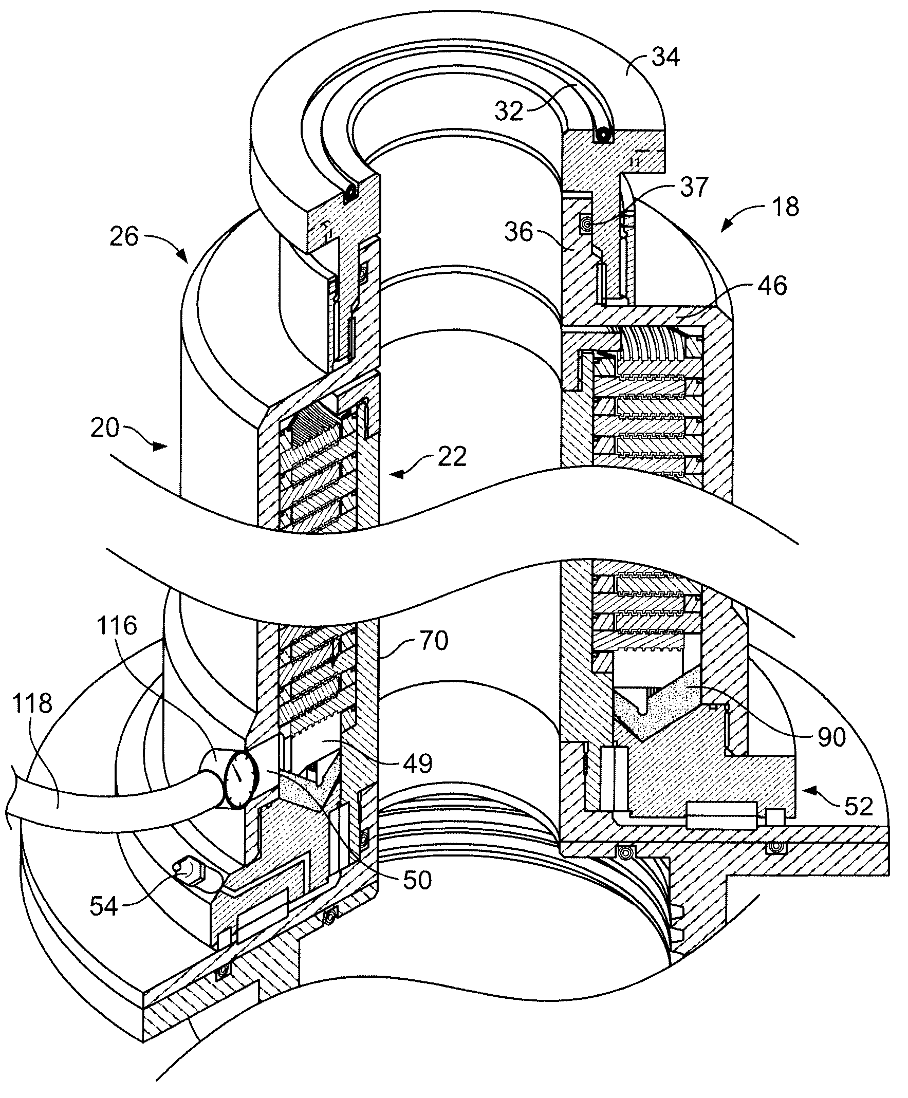
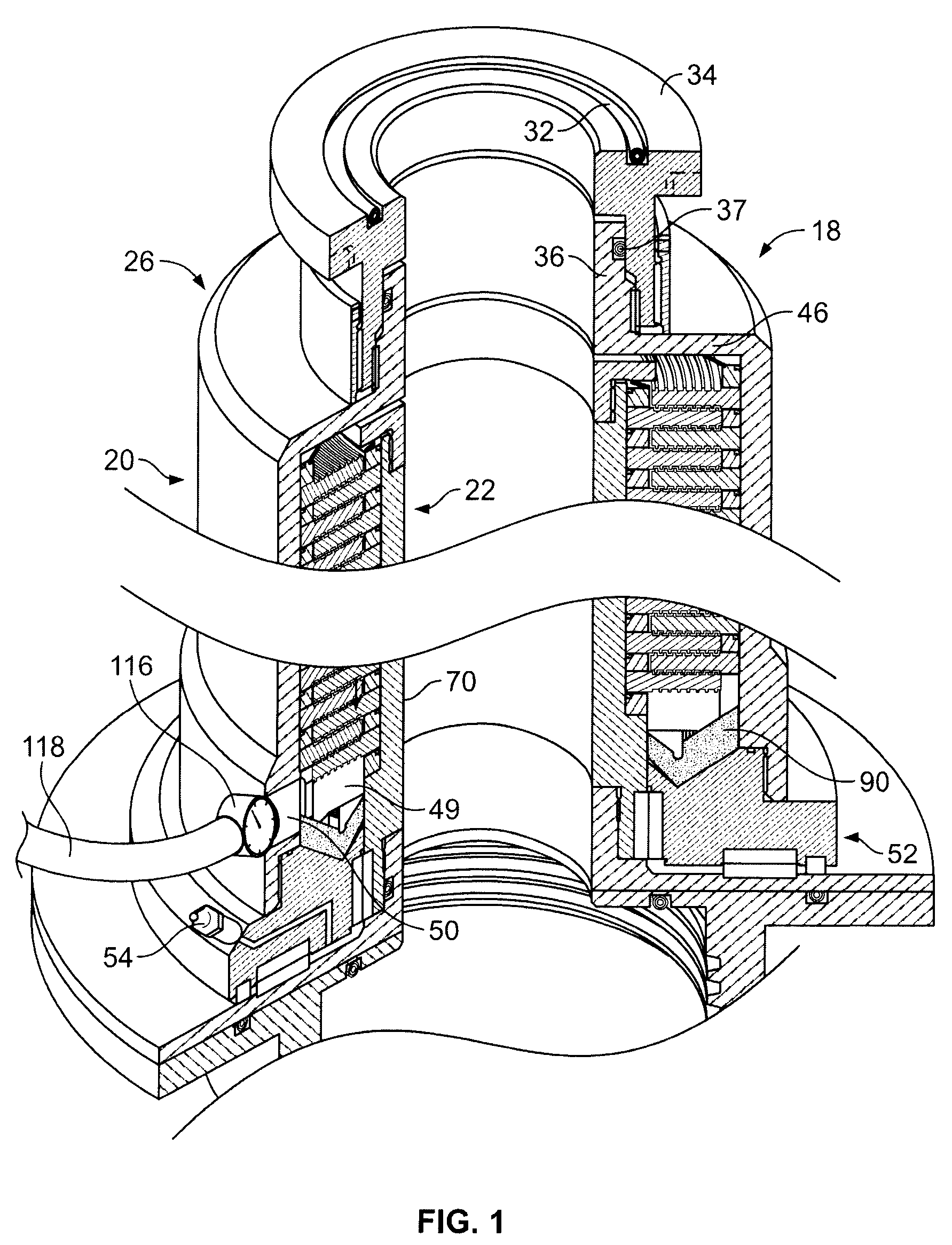
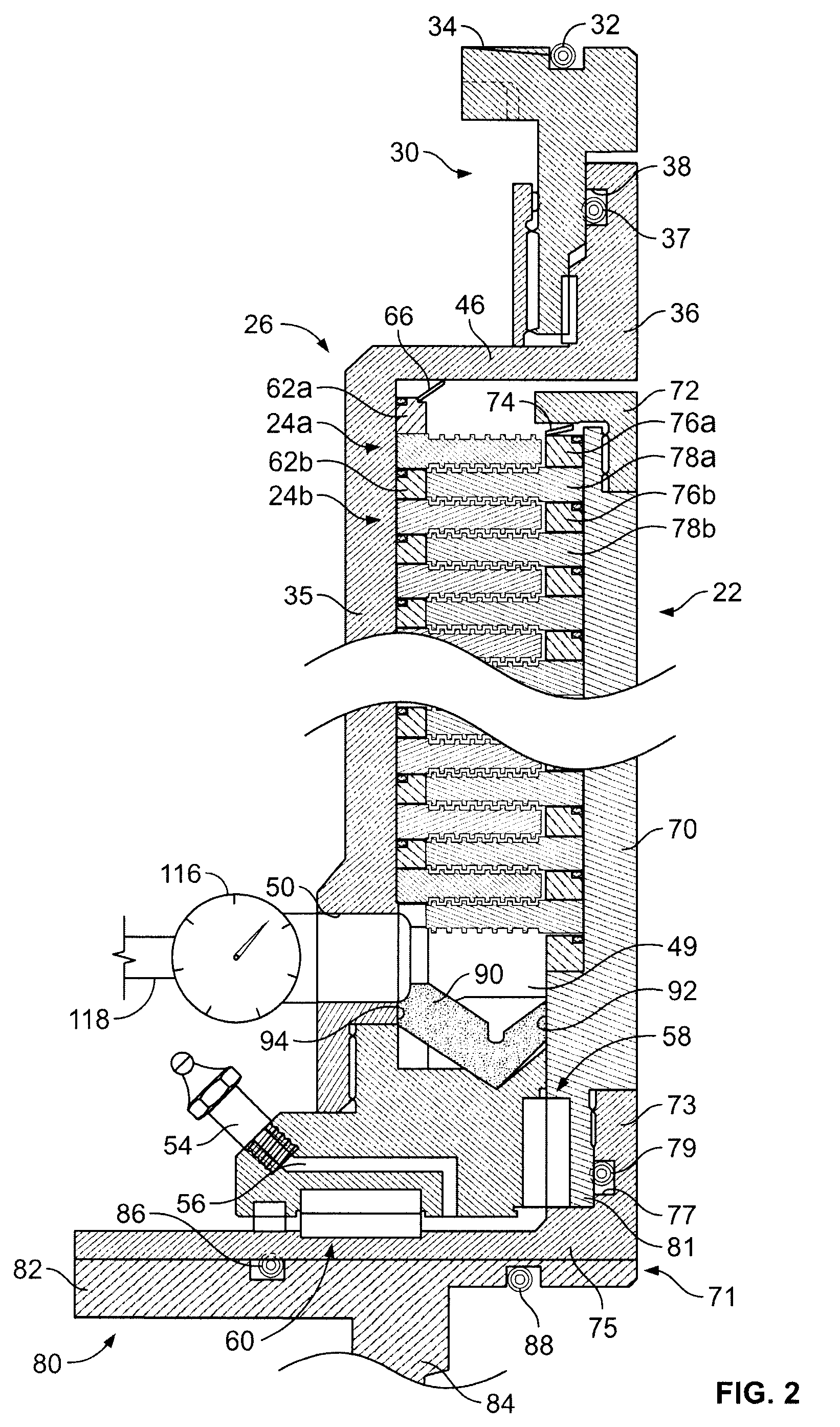
[0039]While the invention may be embodied in a number of different forms, and may employ variations of certain parts, two preferred embodiments of the invention will be described, which include plural rotors and stators that are interleaved with each other and arranged in inner and outer annular housings, and which accommodate a pressure drop from up to 10,000 or more PSI to a much lower level adjacent the outlet.

[0040]Referring now to the drawings in greater detail, there is shown washpipe seal assembly generally designated 18, and this assembly, as best shown in FIGS. 2–4, includes a stator assembly generally designated 20, and a rotor assembly generally designated 22. The stator assembly 20 includes a plurality of discs generally designated 24a, 24b received within a housing generally designated 26. This housing 26 is affixed to an upper connection assembly generally designated 30. This assembly 30 includes a radially outer member with an O-ring 32 on its top surface 34. The inne...


PUM


Abstract

A controlled leakage seal assembly having a first stationary portion adapted to be connected in substantially fluid-tight relation to a source of drilling fluid and a second portion adapted to be connected in substantially fluid-tight relation to a rotary portion including a washpipe. The seal includes a first housing and a stack of radially inwardly extending, spaced apart annular stators, and a second seal housing and stack of spaced apart radially outwardly extending annular rotors interleaved with one another. The seal assembly, a cartridge, permits the first and second housings to rotate relative to each other in substantially fluid-tight relation except for the drilling fluid entering an outlet region at greatly reduced pressure. In a preferred embodiment, the seal is held by a sleeve that permits the cartridge to be removed and replaced while the fluid connections to the sleeve remains.

Description

BACKGROUND OF THE INVENTION[0001]This is a continuation-in-part of prior application Ser. No. 11 / 174,687, filed Jul. 5, 2005, which is hereby incorporated herein by reference in its entirety.[0002]The present invention relates generally to so-called washpipe seals and more particularly, to a washpipe seal which is adapted to permit controlled leakage of a small portion of high pressure drilling fluid which largely passes into the so-called washpipe and into the drill string which is attached thereto. In the oil field industry particularly, a so-called swivel assembly incorporates a seal at the washpipe to confine the major portion of the drilling fluid to the washpipe. This drilling fluid is sometimes colloquially referred to as “drilling mud” or simply “mud.”[0003]In the drilling system, there are high pressure abrasive fluids which are sent down to the bore hole through the washpipe and the drill string, and ultimately to the drill motor which is held at the bottom of the drill st...

Claims


Application Information

Patent Timeline
Patent Type & Authority Patents(United States)
IPC IPC(8): E21B21/06E21B21/00
CPCE21B21/02E21B2033/005E21B2200/01
Inventor MARTIN, KEVIN J.
Owner SKF USA INC
Why Eureka
Try Eureka