Socket for electrical parts

a technology for sockets and electrical parts, applied in the direction of coupling parts, electrical apparatus construction details, coupling device connections, etc., can solve the problems of difficult to make coincident timings of the open/close operation of the contact pins and the rotating operation of the latch member, and achieve the effect of eliminating defects or drawbacks

Inactive Publication Date: 2007-05-08
ENPLAS CORP
View PDF10 Cites 22 Cited by
  • Summary
  • Abstract
  • Description
  • Claims
  • Application Information

AI Technical Summary

Benefits of technology

[0011]Therefore an object of the present invention is to substantially eliminate defects or drawbacks encountered in the prior art mentioned above and to provide a socket for an electrical part in which timings of open / close operation of contact pins and rotating operation of a latch member can accord easily with each other.
[0012]Another object of the present invention is to provide a socket for an electrical part having a reduced number of members or parts such as an operation member.
[0015]According to the socket for an electrical part of the present invention of the characters mentioned above, by vertically moving the movable member, the opening / closing operation of the contact pins and the rotating operation of the latch member can be done directly. Therefore, it may be possible to eliminate an operation member, and the movable member may be pressed by a head disposed on a package insertion / take-out side device, not shown, thus reducing the number of members or parts to be located.
[0016]In addition, since the opening / closing operation of the contact pins and the rotating operation of the latch member are performed by the vertical movement of the movable member, there is less influenced by errors in molding or assembling the members, and the timings of these operations can be easily made coincident with each other.

Problems solved by technology

For this reason, it is essential to locate such operation member, and in addition, it is difficult to make coincident timings of the open / close operation of the contact pins and rotating operation of the latch member.
Thus, it is difficult to make coincident the timings of the open / close operation of the contact pins and rotating operation of the latch member.

Method used


Image

  • Socket for electrical parts
  • Socket for electrical parts
  • Socket for electrical parts

Examples


first embodiment

[0039][First Embodiment]

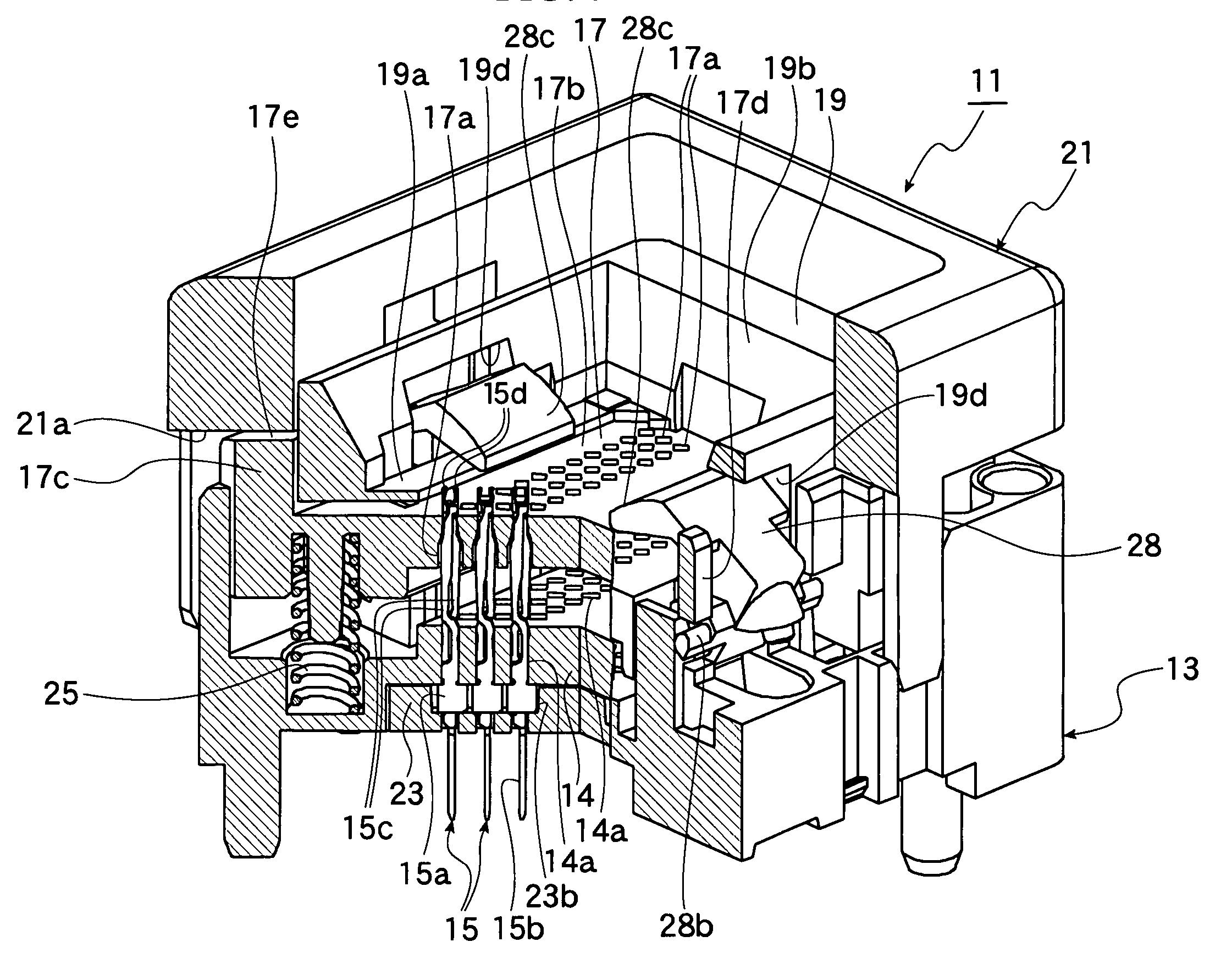
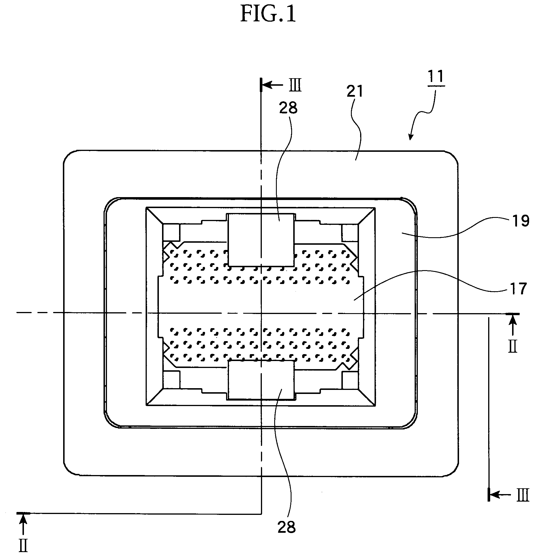
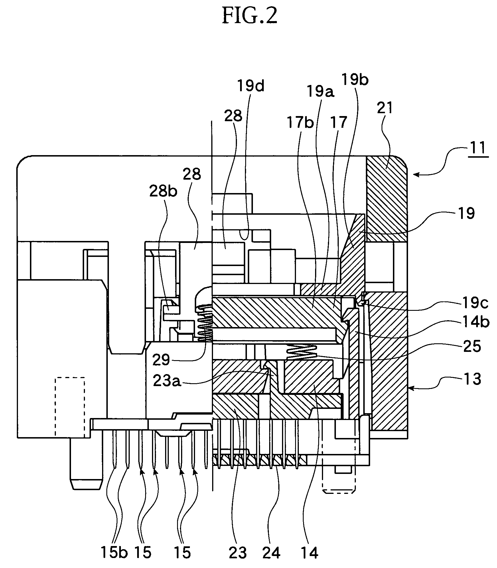
[0040]FIGS. 1 to 14 represent a first embodiment of an IC socket as a socket of an electrical part. Further, it is first to be noted that terms “right”, “left”, “upper”, “lower” and the like terms are used herein with reference to the illustrated state on the drawings or in a generally using state of the IC socket of this kind.

[0041]With reference to FIGS. 1 to 14, reference numeral 11 denotes an IC socket as “a socket for an electrical part”, which is a socket for establishing an electrical connection between a solder ball 12b as a terminal of an IC package 12 as “an electrical part” and a printed circuit board, not shown, of a measuring device such as tester, for carrying out a performance test of the IC package 12.

[0042]The IC package 12 is so-called an BGA (Ball Grid Array) type, such as shown in FIGS. 6, in which terminals 12b, each in a spherical shape, are arranged to a lower surface of a square package body 12a of the IC package 12 so as to protrude t...

second embodiment

[0076][Second Embodiment]

[0077]FIGS. 15 to 19 represent the second embodiment of the present invention.

[0078]The second embodiment differs from the first embodiment in that an operation member 21 such that in the first embodiment is not located, and the guide member only includes the support piece 19a and does not include the guide 19b.

[0079]In such structure of the second embodiment, the pressed surface 17e (horizontal surface) formed on the upper surface of the projection piece 17c of the movable member 17 is directly pressed by a head disposed on the package insertion / take-out device side, not shown.

[0080]Accordingly, with no use of the operation member 21, the number of constitutional members or parts can be reduced, and in addition, the surface 17e to be pressed has a horizontal surface perpendicular to the moving direction (vertical direction), so that the head side can be simply constructed, thus improving the strength thereof, and furthermore, there is not adopted a sliding...


PUM


Abstract

A socket for an electrical part includes a socket body to which an electrical part is accommodated, the socket body having a base portion to which a number of elastic contact pins are arranged, a movable member disposed to the socket body above the base portion to be vertically movable, contact portions, between which a terminal of the electric part is inserted, formed to the contact pins being opened or closed, and a latch member provided for the socket body so as to press the electrical part accommodated to the socket body. The latch member is disposed to be movable between a first position at which the electrical part is pressed and a second position at which the latch member is retired from a line along which the electrical part is accommodated or taken out. The latch member is moved by a pressing portion formed to the movable member.

Description

BACKGROUND OF THE INVENTION[0001]1. Field of The Invention[0002]The present invention relates to a socket for an electrical part for detachably holding an electrical part such as a semiconductor device (called as “IC package” hereinlater).[0003]2. Related Art[0004]In a known art, there has been provided an IC socket, as “socket for an electrical part” for detachably holding an “IC package” as an electrical part such as disclosed in Japanese Laid-Open (KOKAI) Patent Publication No. 2002-8809.[0005]The IC package disclosed in this publication includes a number of solder balls, as terminals, which are arranged on a lower surface of the IC package so as to protrude therefrom in an lattice arrangement including vertical rows Y and horizontal lines X.[0006]The IC socket, on the other hand, includes a socket body in which the IC package is accommodated and which is provided with a number of contact pins contacting the terminals of the IC package. The socket body is also provided with a mov...

Claims


Application Information

Patent Timeline
Patent Type & Authority Patents(United States)
IPC IPC(8): H01R13/62
CPCH05K7/1084
Inventor HAYAKAWA, KENJI
Owner ENPLAS CORP
Why Eureka
Try Eureka