Sensor device, particularly for controlling lighting devices of a motor vehicle

a technology of motor vehicles and sensors, which is applied in the direction of optical elements, instruments, transportation and packaging, etc., can solve the problems of achieve the effect of optimally controlling the peripheral devices, small and compact, and not restricting the visual range of the driver

Inactive Publication Date: 2007-05-08
ROBERT BOSCH GMBH
View PDF14 Cites 5 Cited by
  • Summary
  • Abstract
  • Description
  • Claims
  • Application Information

AI Technical Summary

Benefits of technology

[0003]The sensor device of the present invention has the advantage that, due to a diffractive element, which preferably takes the form of a hologram, a very small and compact sensor device is produced which does not restrict the visual range of the driver, and nevertheless, optimally controls the peripheral devices. To that end, the diffractive element is arranged in the receiver region of a receiver, so that the receiver receives radiation from the surroundings, e.g. sunlight or artificial light from specific relevant space areas, and relays to a control device.
[0005]It is particularly advantageous if a plurality of receptions are provided which detect radiation from various spatial reception regions, and a single diffractive element is provided for all reception regions. The individual brightness signals from the various spatial reception regions are thereby each available individually, making it possible to optimally control the individual lighting devices or other peripheral devices of the motor vehicle. Because a single diffractive element is provided for all reception regions, particularly for a global and directional sensor system, the costs of a sensor device according to the present invention are reduced to a minimum.
[0008]It is particularly advantageous if the diffractive element is controllable, so that the reception region is adjustable as a function of control signals. In this way, for example, measurements may be carried out in alternation in the forward direction and in the direction of surface normal of the window, and thus information may be obtained from several different reception regions with the aid of a single receiver and a single diffractive element. This yields a more precise control of the peripheral devices, while the costs for the sensor device are only increased a little. In this context, it is particularly advantageous if the diffractive element is controllable periodically.

Problems solved by technology

Since the lighting conditions in the forward direction of the vehicle are particularly relevant for controlling the lighting devices, the light-guiding member must be arranged on the windshield of the motor vehicle, which restricts the visual range of the driver because of the expansion of the sensor device.

Method used


Image

  • Sensor device, particularly for controlling lighting devices of a motor vehicle
  • Sensor device, particularly for controlling lighting devices of a motor vehicle

Examples


Embodiment Construction

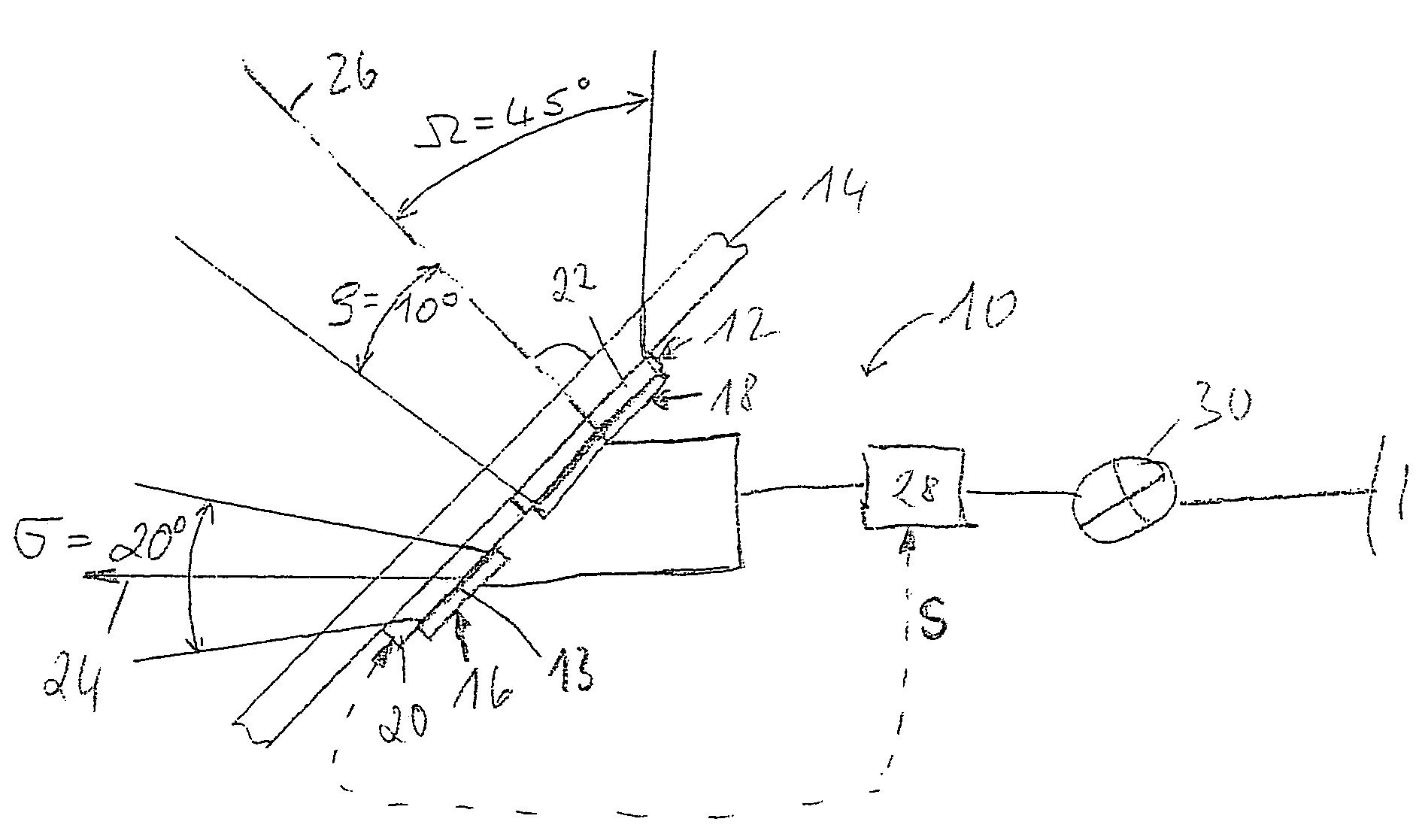
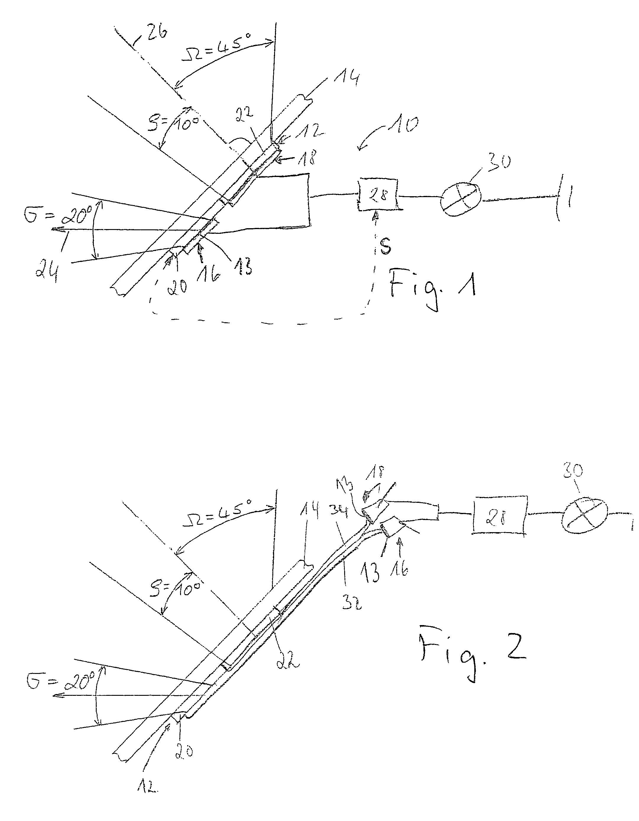
[0012]FIG. 1 shows a schematic cross-sectional representation of a sensor device according to the present invention. Sensor device 10 is made essentially of a diffractive element 12 formed as a hologram film. This hologram film 12 is pasted or fastened in another manner on a window 14, e.g., the windshield of a motor vehicle; naturally, diffractive element 12 may also be disposed in window 14.

[0013]Light-sensitive reception elements 13 are positioned as receivers 16, 18 on the side of diffractive element 12 facing away from window 14. Diffractive element 12 is divided into a first region 20 and a second region 22, and is formed in such a way that receives light from the forward direction of the motor vehicle, indicated by arrow 24, and images on first receiver 16. An acceptance cone a having a width of approximately 20° is thereby formed, which detects radiation from the forward direction. Therefore, here less light radiation is detected in front of a tunnel entrance than on the ope...


PUM

PropertyMeasurementUnit
brightnessaaaaaaaaaa
transparentaaaaaaaaaa
solid-angleaaaaaaaaaa

Abstract

A sensor device is proposed, particularly for controlling lighting devices of a motor vehicle, having at least one receiver for receiving radiation from at least one receiver region, and a control device which is capable of controlling peripheral devices; a diffractive element, able to be attached to a window and formed preferably as a hologram, is provided which is arranged in the receiver region of the receiver.

Description

FIELD OF THE INVENTION[0001]The present invention relates to a sensor device, particularly for controlling lighting devices of a motor vehicle.BACKGROUND INFORMATION[0002]Numerous sensor devices are already known which are used for controlling lighting devices of motor vehicles. Such a sensor device is described, for example, in the German Published Patent Application No. 199 33 642. It has a bulky light-guiding member made of transparent plastic that is secured on the window of a motor vehicle via a coupling medium. This light-guiding member images the radiation of light from various solid-angle regions onto receivers, which, for their part, control the lighting devices via a suitable control device. Since the lighting conditions in the forward direction of the vehicle are particularly relevant for controlling the lighting devices, the light-guiding member must be arranged on the windshield of the motor vehicle, which restricts the visual range of the driver because of the expansio...

Claims


Application Information

Patent Timeline
Patent Type & Authority Patents(United States)
IPC IPC(8): H01L27/00G01N21/55G08G1/00G02B5/32B60Q1/02B60Q1/14
CPCB60Q1/1423B60Q2300/314B60Q2300/3321B60Q1/14
Inventor MICHENFELDER, GEBHARDSCHNEIDER, ANDREAS
Owner ROBERT BOSCH GMBH
Why Eureka
Try Eureka