Shape changing structure

a shape-changing structure and structure technology, applied in the field of structures, can solve the problems of chevrons also generating drag and loss of thrust, kinematic mechanisms, and unable to be located on the external surfaces of nacelles and chevrons

Active Publication Date: 2007-05-15
THE BOEING CO
View PDF62 Cites 70 Cited by
  • Summary
  • Abstract
  • Description
  • Claims
  • Application Information

AI Technical Summary

Problems solved by technology

Although the chevrons have been shown useful to attenuate noise, since they interact directly with the flow streams generated by the engine, the chevrons also generate drag and loss of thrust.
However, due to the aerodynamics necessities and extreme operational conditions associated with the engine nacelle and chevrons, kinematic mechanisms and the related actuators that would be needed to deploy the chevrons can not be located on external surfaces of the nacelle and chevrons.
Furthermore, neither the nacelle structure nor the chevron structures provide adequate internal space to accommodate such kinematic mechanisms and actuators.

Method used


Image

  • Shape changing structure
  • Shape changing structure
  • Shape changing structure

Examples


Embodiment Construction

[0019]The following description of the preferred embodiments is merely exemplary in nature and is in no way intended to limit the invention, its application or uses. Additionally, the advantages provided by the preferred embodiments, as described below, are exemplary in nature and not all preferred embodiments provide the same advantages or the same degree of advantages.

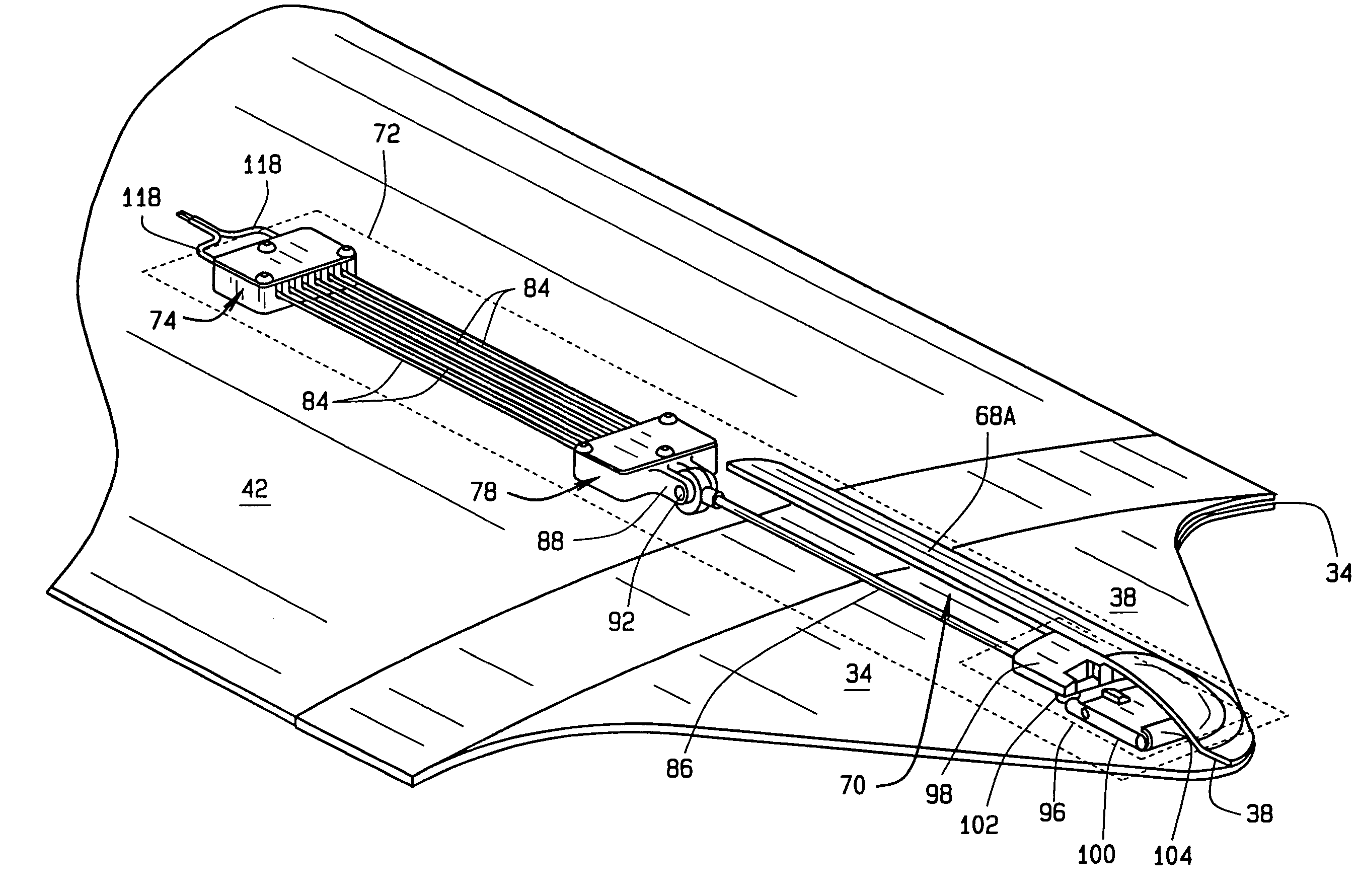
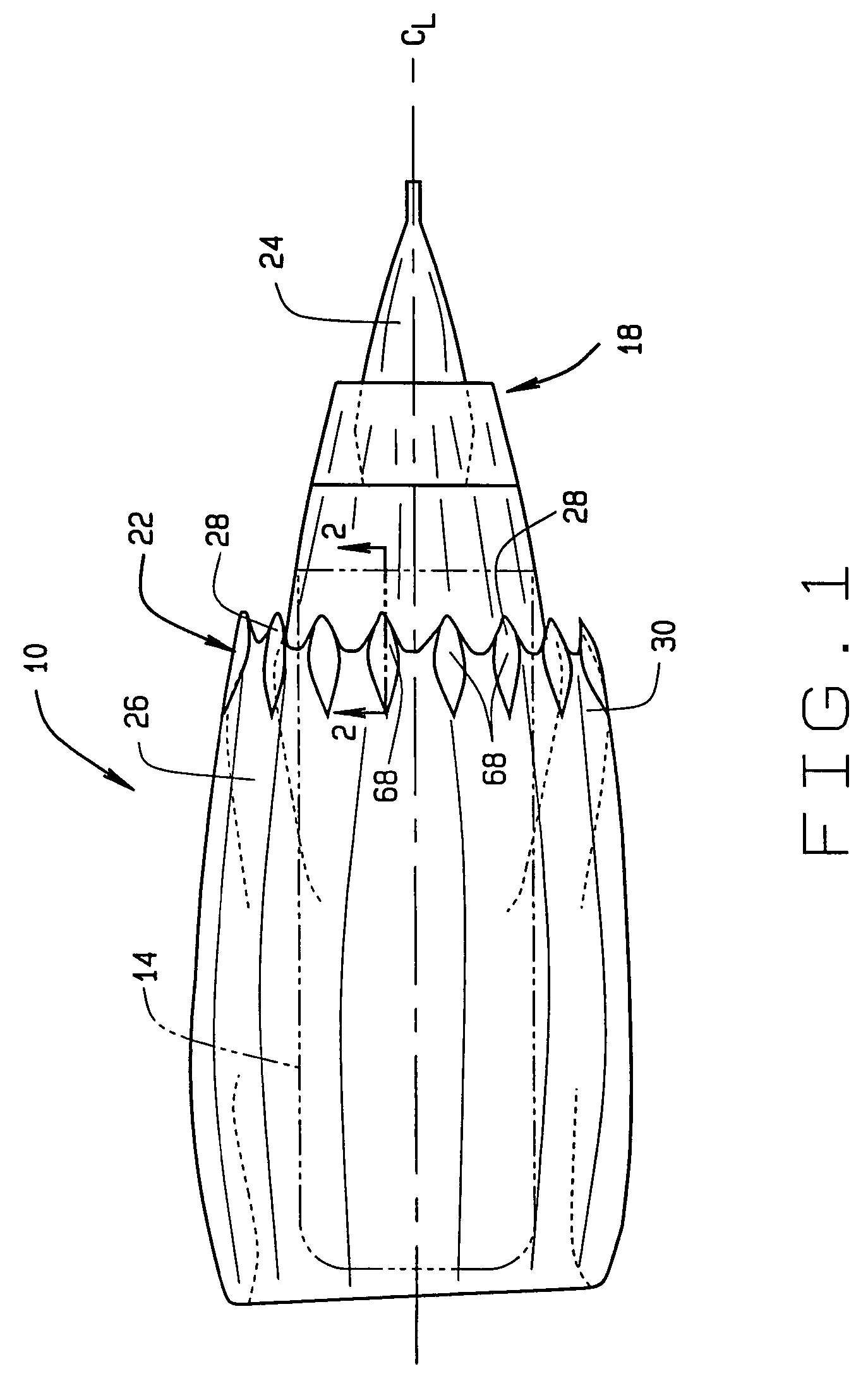
[0020]FIG. 1, illustrates an exemplary structure 10, shown as a jet engine nacelle, in accordance with a preferred embodiment of the present invention. Although the structure 10 and associated features and components will be described herein with respect to a jet engine nacelle, it should be understood that the present invention is applicable to any structure configured to change shape, form or position, and that the specific references herein to the jet engine nacelle are merely exemplary. For example, the present invention could be applicable to environmental control system air flow structures, automotive fuel and ...


PUM


Abstract

In one preferred embodiment, a structure is provided that includes a body having a first wall and a second wall. At least one appending component extends from an end of the body and includes a first skin and second skin. The structure additionally includes at least one actuator positioned within a cavity formed in the body first wall and the appending component second skin. The actuator includes at least one shape memory alloy (SMA) wire adapted to constrict when activated to move the first skin of the appending component from a first position to a second position.

Description

FIELD OF INVENTION[0001]The present invention relates to structures that are adapted to change shape or position for operational purposes. More particularly, the present invention relates to structures configured to alter shape or position without the use of electric or hydraulic actuators to pivotally rotate hinged components.BACKGROUND OF THE INVENTION[0002]There is a growing desire in the design of various structures to have structures that can change shape or position without the use of bulky mechanical devices. For example, in mobile platform design, e.g. aircraft, automobiles, trains and ships, to have structures that can change shape or position while the mobile platform is in operation. Such shape or positional changes are often desirable to meet fluctuating aerodynamic needs throughout the duration of the mobile platform's travel. Typically, such dynamic shaping is performed through specific control structures such as flaps, spoilers, ailerons, elevators, rudders, etc. Thes...

Claims


Application Information

Patent Timeline
Patent Type & Authority Patents(United States)
IPC IPC(8): B64C13/00
CPCF02K1/1207F02K1/123F02K1/386F02K1/48F02K9/805F05D2300/505
Inventor WOOD, JEFFREY H
Owner THE BOEING CO
Why Eureka
Try Eureka