
Liquid-discharging apparatus, and density adjusting method and system of the same

a technology of liquid-discharging apparatus and density adjustment method, which is applied in the direction of inking apparatus, digitally marking record carriers, instruments, etc., can solve the problems of inability to completely solve the discharging unit, density unevenness, and inability to control the amount of ink droplets during one discharging operation, so as to reduce printing speed, increase hardware, and memory

Inactive Publication Date: 2007-05-15
SONY CORP
View PDF7 Cites 30 Cited by
  • Summary
  • Abstract
  • Description
  • Claims
  • Application Information

AI Technical Summary

Benefits of technology

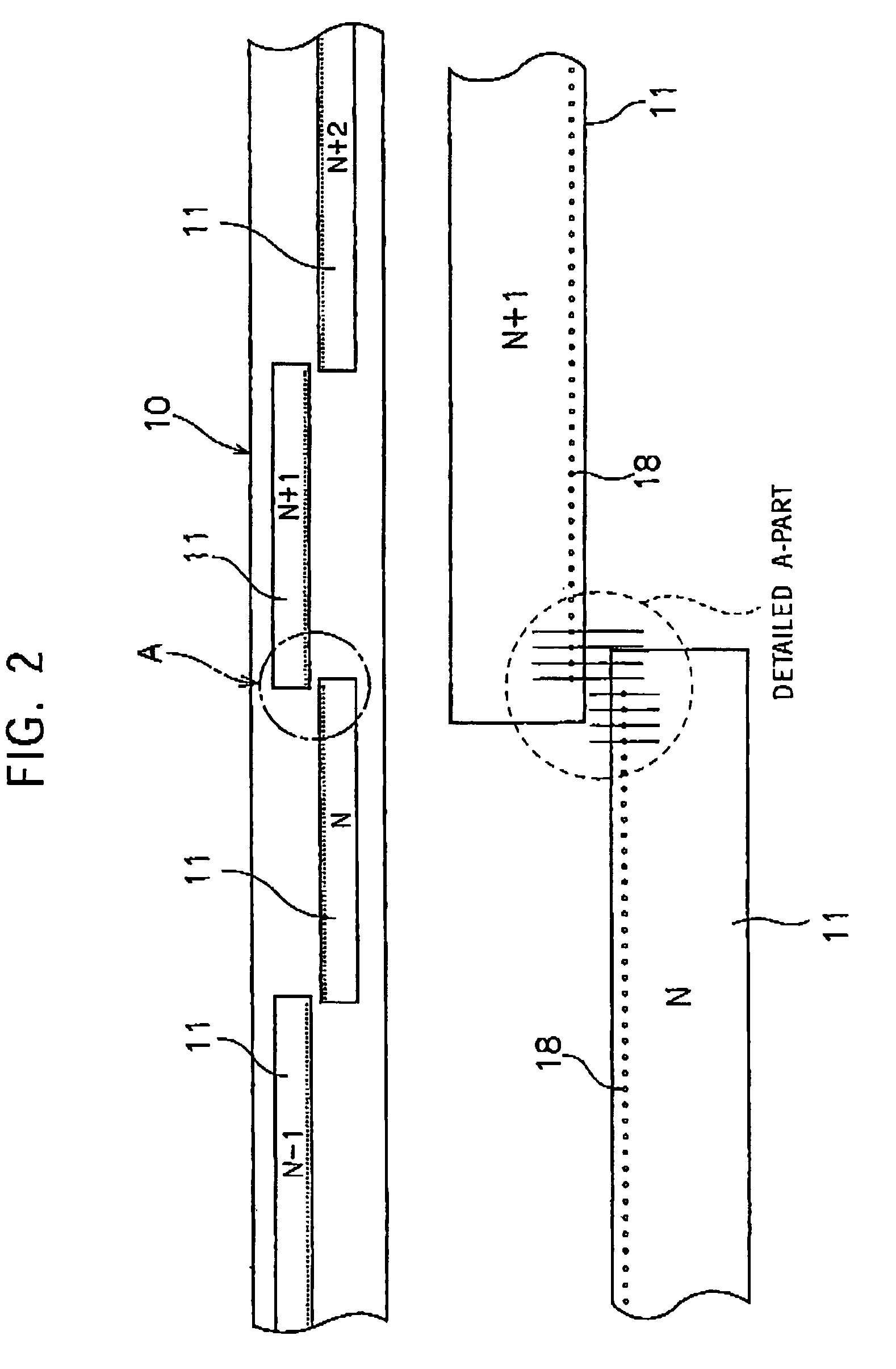
The present invention provides a method for adjusting density unevenness in a liquid-discharging apparatus without reducing printing speed or increasing hardware requirements. The method involves obtaining density information and the relationship between the number and density of discharged droplets for each pixel train. A density-measuring pattern is formed by discharging a predetermined number of droplets from each liquid-discharging unit, and the density of the pattern is scanned. Based on the obtained density information, the number of droplets discharged from the liquid-discharging units is adjusted to achieve a uniform and constant density for each pixel train. This allows for precise control over the density of each pixel train, improving the quality of the printed image.

Problems solved by technology

Unfortunately, the head of the inkjet printer, for example, including thermal liquid-discharging units, can discharge only a constant amount of ink droplet from each nozzle during one discharging operation, except for a special head including a special discharging mechanism formed by utilizing the piezo technology.
In other words, a discharge amount of an ink droplet during one discharging operation cannot be controlled.
Unfortunately, according to the above-mentioned overprinting method, problems such as density unevenness caused by a variation in discharging characteristics of the liquid-discharging units can not be completely solved.
Firstly, a problem arises from a certain limitation of an ink-absorbing amount of a sheet of printing paper.
That is, when a dot is superimposed beyond the limitation of an ink-absorbing amount of a sheet of printing paper, the dot is unlikely dried, and also, to make matters worse, ink of the dot spreads over the adjacent dots and generates color mixture with that of the adjacent dots, thereby leading to a failure in achieving an expected density gradation characteristic.
Unfortunately, the foregoing known method for correcting density unevenness is needed to process an input image, and, especially when an input image including a large amount of data is required to be processed, a longer period of time for processing the input image is needed before printing, thereby resulting in a reduced printing speed.
Improvement in the printing speed incurs an increase in hardware, memory, and the like, and hence causes a larger size of the printer.

Method used


Image

  • Liquid-discharging apparatus, and density adjusting method and system of the same
  • Liquid-discharging apparatus, and density adjusting method and system of the same
  • Liquid-discharging apparatus, and density adjusting method and system of the same

Examples


Embodiment Construction

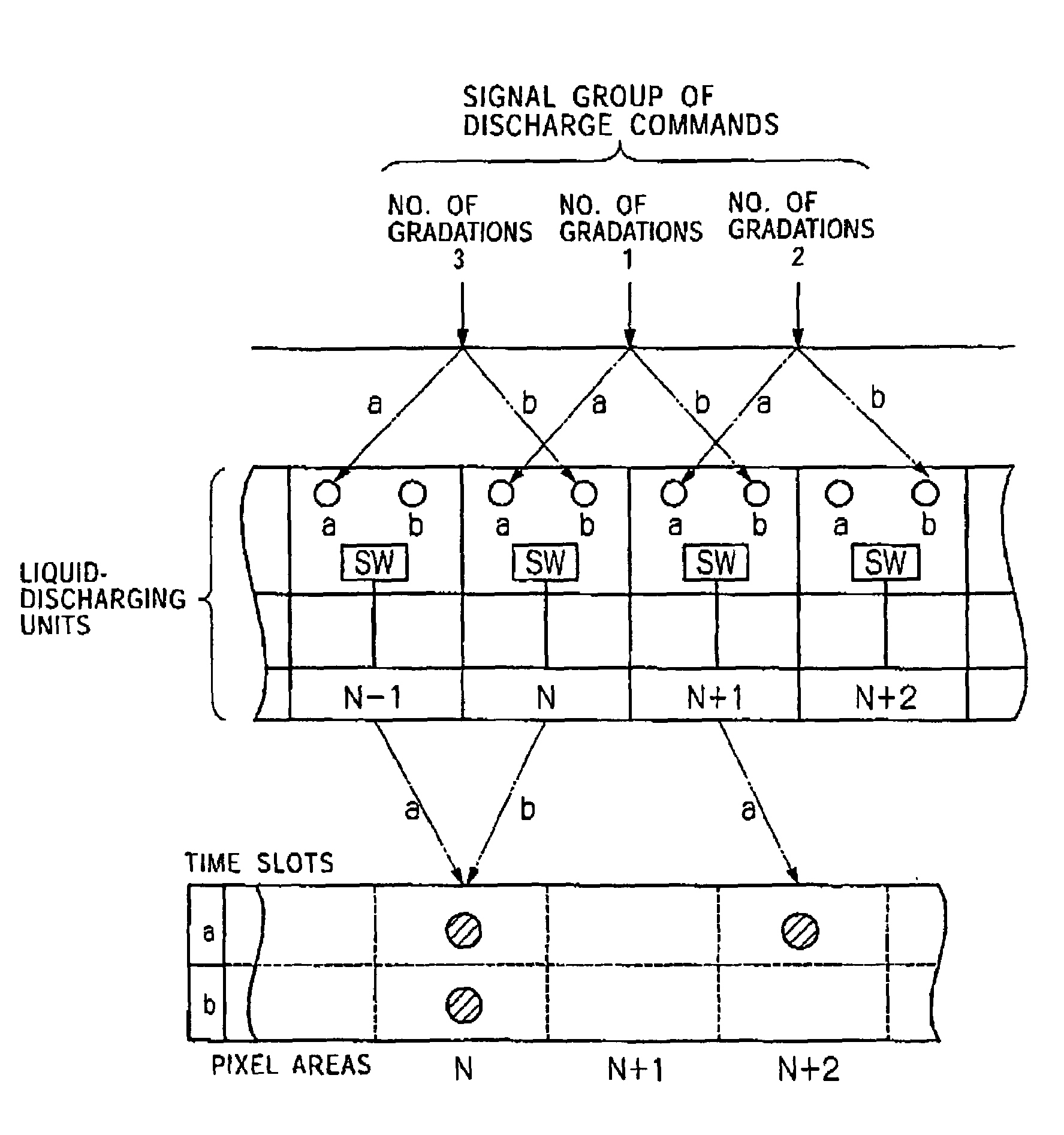
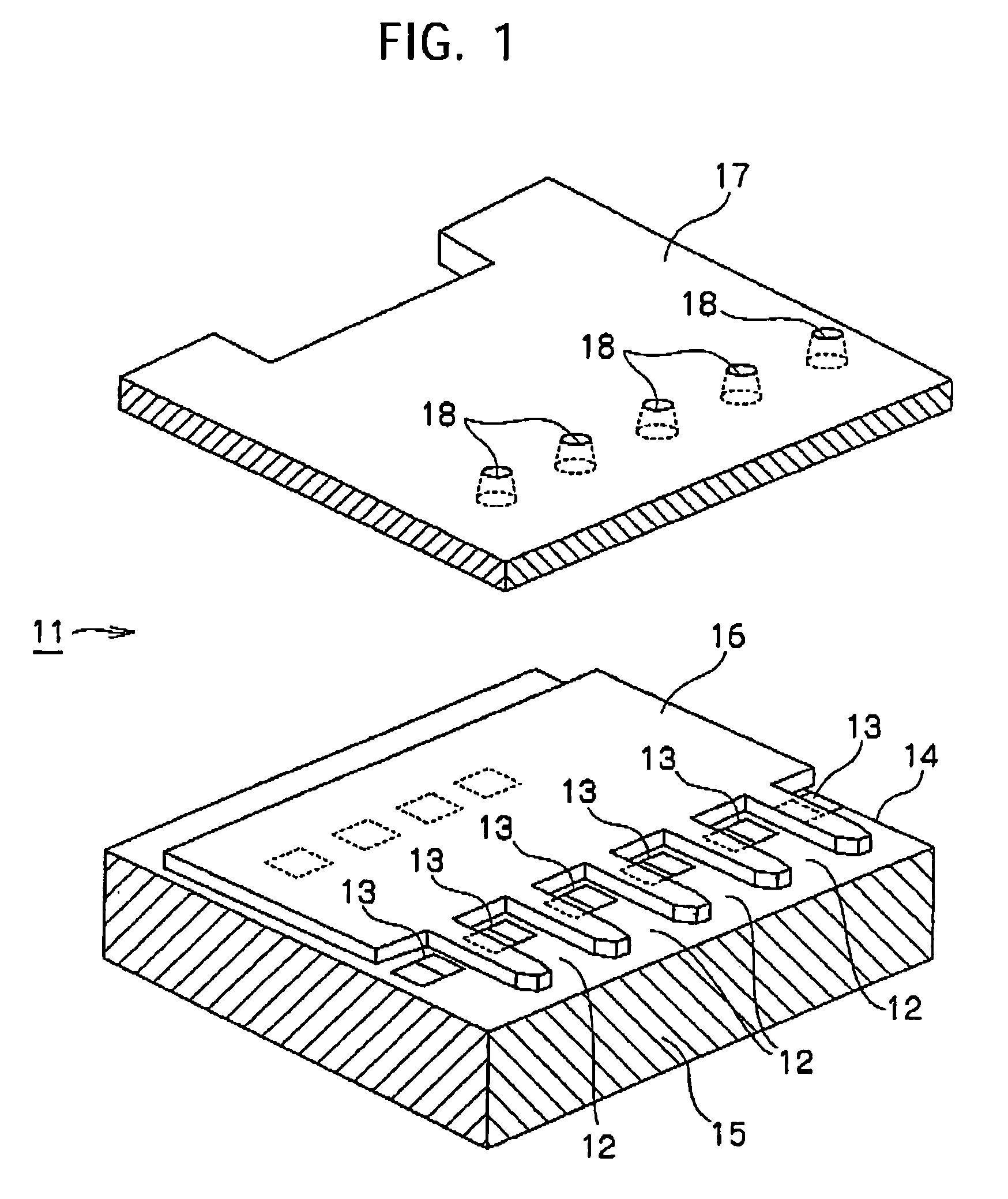
[0044]Preferred embodiments of the present invention will be described with reference to the attached drawings. In the following descriptions an inkjet printer (hereinafter, simply referred to as a printer) is used as a liquid-discharging apparatus according to the present invention by way of example.

[0045]In the description, a term “ink droplet” means a very small amount (for example, a few picolillters) of ink (liquid) discharged from a nozzle 18 of a liquid-discharging unit, which will be described later.

[0046]A term “dot” means one form of an ink droplet landed on a recording medium such as a sheet of printing paper.

[0047]Also, a term “pixel” is a minimum unit of an image, and, in addition, a term “pixel area” means an area in which a pixel is formed.

[0048]Thus, when a predetermined number (zero, one, or a plurality of pieces) of droplets are landed in a single pixel area, a pixel (1-step gradation) with no pixel, a pixel (2-step gradation) with a single dot, or a pixel (3 or mo...


PUM


Abstract

A density-adjusting method of a liquid-discharging apparatus having a head including a plurality of juxtaposed liquid-discharging units having respective nozzles, forming dots by landing droplets discharged from the nozzles onto a droplet-landing object, and providing half tones by arranging a dot array is provided. A density-measuring pattern including all pixel trains lying in the main scanning direction with a constant density is formed, the density of the pattern is scanned so as to obtain density information and the relationship between the number and the density of droplets with respect to each pixel train. Upon receipt of a discharge command signal, based on the obtained data with respect to each pixel train, the density of the pixel train corresponding to the discharge command signal is adjusted by making the number of droplets to be actually discharged from the nozzles different from that of droplets discharged according to the discharge command signal.

Description

[0001]The present application claims priority to Japanese Patent Application JP2003-156449, filed in the Japanese Patent Office Jun. 2, 2003; the entire contents of which is incorporated herein by reference.BACKGROUND OF THE INVENTION[0002]1. Field of the Invention[0003]The present invention relates to a liquid-discharging apparatus including a head equipped with a plurality of juxtaposed liquid-discharging units having respective nozzles, forming dots by landing droplets discharged from the nozzles onto a droplet-landing object, and providing half tones by arranging a dot array, and also relates to a density adjusting method and a density adjusting system for adjusting the density of the dots. More particularly, the present invention is relates to a technique for adjusting density unevenness when the unevenness occurs due to a variation in discharging characteristics of the liquid-discharging units.[0004]2. Description of the Related Art[0005]An inkjet printer is known as one of co...

Claims


Application Information

Patent Timeline
Patent Type & Authority Patents(United States)
IPC IPC(8): B41J2/205B41J2/01B41J2/21
CPCB41J2/2054B41J2/2121B41J2202/20B41J2/01B41J2/07B41J2/135B41J2/36B41J3/543
Inventor EGUCHI, TAKEOTAKENAKA, KAZUYASUTAKAHASHI, TAKANORIUJIIE, ICHIRO
Owner SONY CORP
Learn More