Water floor broom with clean-up squeegee

a technology of floor cleaning and water spray, which is applied in the direction of cleaning using liquids, hand devices, ways, etc., can solve the problems of affecting the wide-spread or efficient use of water floor cleaning brooms, affecting the cleaning effect, so as to achieve the effect of convenient and efficient cleaning

Active Publication Date: 2007-05-15
FNA GROUP INC
View PDF5 Cites 32 Cited by
  • Summary
  • Abstract
  • Description
  • Claims
  • Application Information

AI Technical Summary

Benefits of technology

[0003]It is an object of the present invention to provide a water floor broom that is adapted for easier and more efficient usage in cleaning of floors.
[0004]Another object is to provide a water floor broom as characterized above which is adapted to substantially minimize or eliminate the necessity for later mopping of water directed onto the floor during cleaning.
[0005]A further object is to provide a water floor broom of the above kind that is relatively light in weight and economical in construction.
[0006]Still another object is to provide a water floor broom of the foregoing type that is operable for effectively cleaning floors with lesser quantities of water or other cleaning liquids. A related object is to provide a water floor broom of such type which is operable by a relatively lighter weight and more economical electric powered pressure washer pump.

Problems solved by technology

Conventional water floor brooms suffer from a number of drawbacks which detract from their wide-spread or efficient usage.
At the outset, since water floor brooms often are designed for commercial usage, they can be heavy and massive, making it difficult to manually use or manipulate over long periods of time.
Moreover, to provide adequate liquid flow and pressurization for thorough cleaning, such water floor brooms typically are used with gas powered pressure washer pumps, which also are relatively heavy, cumbersome to handle, and expensive to manufacture.
A further drawback of existing water floor brooms is that while they can be effective in cleaning floors, considerable water is directed onto the floor which must later be mopped up or otherwise disposed of to complete the cleaning task.

Method used


Image

  • Water floor broom with clean-up squeegee
  • Water floor broom with clean-up squeegee
  • Water floor broom with clean-up squeegee

Examples


Embodiment Construction

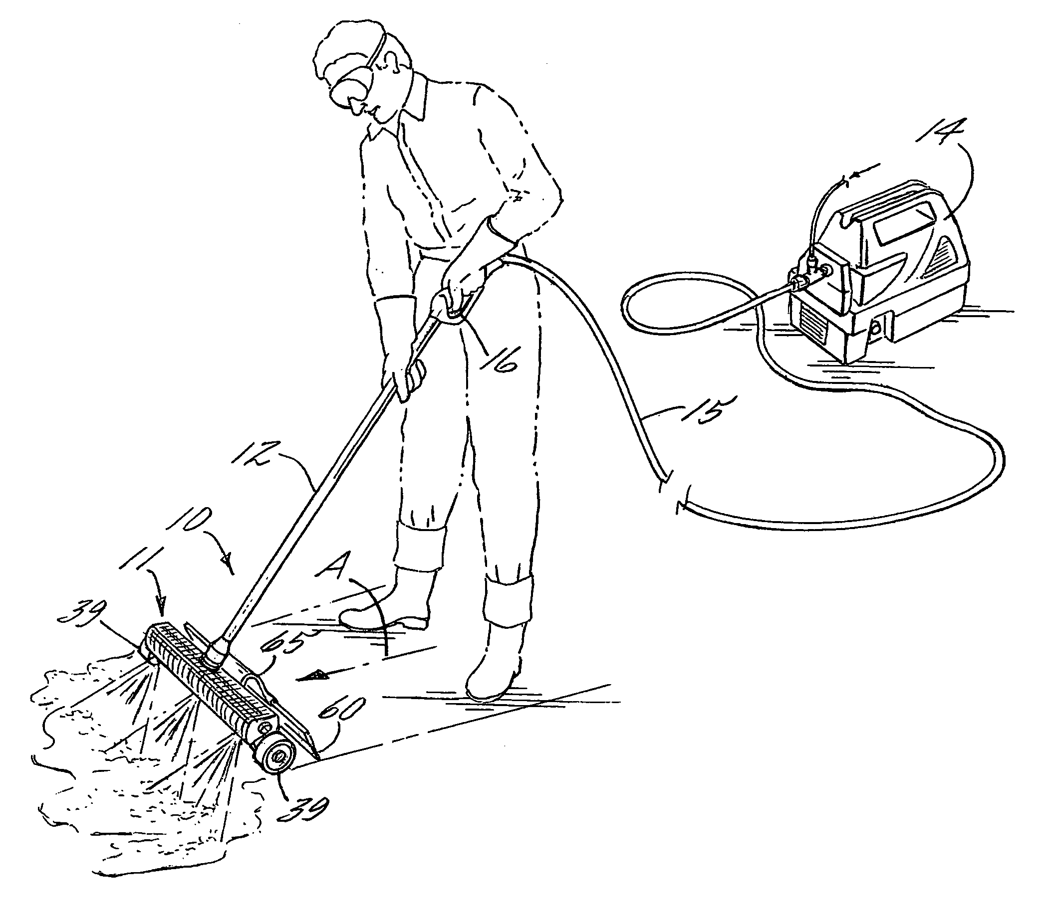
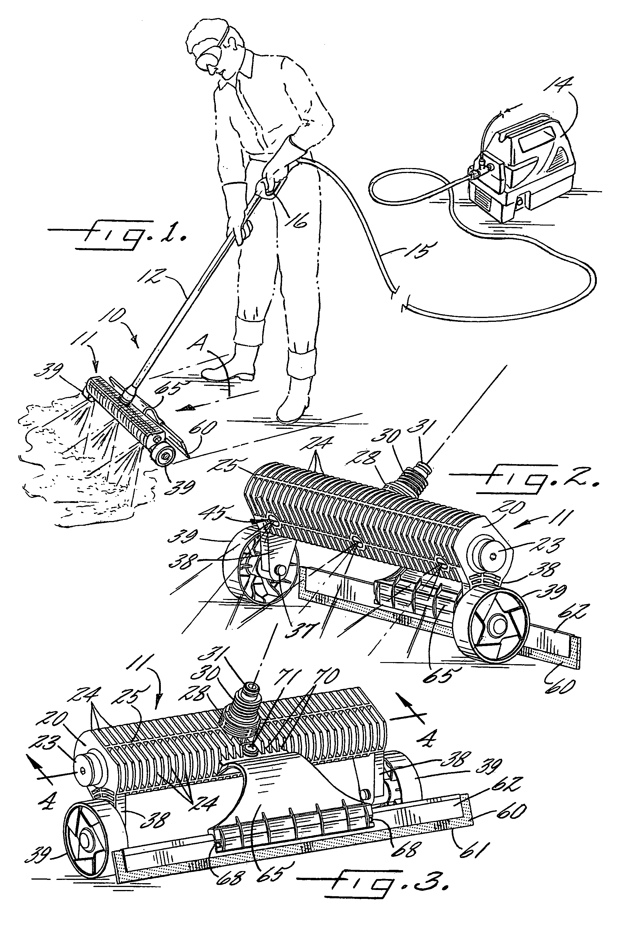
[0016]Referring now more particularly to the drawings, there is shown an illustrative water floor broom 10 in accordance with the invention. The water broom 10 basically comprises a spray head 11 that is moveable along the floor, an elongated handle 12 fixed in upstanding relation to the spray head 11 for moving the spray head 11 along the floor, and a pressure washer pump 14 having a high pressure fluid transfer hose 15 with a control wand or gun 16 at an end thereof for supplying pressurized liquid to the spray head 11 through the handle 12. The pressure washer pump 14 may be of a conventional type, preferably a light weight electric powered pressured washer, capable of delivering a liquid flow stream up to at least 1.5 gpm at 1,100 psi. The gun 16 may be connected to the upper end of the handle 12 with an appropriate quick disconnect bayonet coupling effective for providing a releaseable fluid type connection therebetween. Through operation of the pressure washer pump 14, a clean...


PUM


Abstract

A water floor broom having a spray head that defines an elongated manifold liquid flow passageway communicating with a plurality of liquid spray nozzles, a handle fixed to said body defining a liquid flow passageway communicating with said spray head, and a power washer coupled to said handle for directing pressurized liquid via said handle to said spray head for discharge from the spray nozzles for cleaning a floor surface. The spray head has a light weight, rigid plastic construction that can be operated with lesser quantities of cleaning liquids, and a squeegee blade secured rewardly of the spray head for simultaneously scraping and cleaning water from the floor surface directed onto the floor surface by the spray head for minimizing or eliminating subsequent cleanup.

Description

FIELD OF THE INVENTION[0001]The present invention relates generally to floor cleaning devices, and more particularly, to water spray floor cleaning devices sometimes referred to in the industry as water floor brooms.BACKGROUND OF THE INVENTION[0002]Water floor brooms are known of the type which have a cleaning head that is movable along the floor and which has a plurality of downwardly directed liquid spray nozzles communicating with a manifold liquid flow passageway in the cleaning head, which in turn communicates with a liquid flow passageway in a handle of the broom. The handle is releaseably coupled to the wand of a conventional power washer pump that is operable for directing a pressurized liquid through the handle and cleaning head for discharge from the nozzles onto the floor in pressurized liquid flow streams as the cleaning head is manually moved along the floor by an operator by means of the handle. Conventional water floor brooms suffer from a number of drawbacks which de...

Claims


Application Information

Patent Timeline
Patent Type & Authority Patents(United States)
IPC IPC(8): A47L13/26A46B11/00A47L13/30A47L7/00B05B9/00
CPCA47L13/11B05B1/202B08B3/024E01H1/101
Inventor ALEXANDER, GUSCHEN, KAREN
Owner FNA GROUP INC
Why Eureka
Try Eureka