Fixing and release systems

a technology of fixing and release system, applied in the direction of sheet joining, ropes and cables for vehicles/pulleys, dowels, etc., can solve the problems of reducing and affecting the repair effect of the element being fixed, so as to achieve the effect of reducing the subsequent treatment and increasing the profit of the manufacturer

Inactive Publication Date: 2007-05-15
TELEZYGOLOGY
View PDF108 Cites 51 Cited by
  • Summary
  • Abstract
  • Description
  • Claims
  • Application Information

AI Technical Summary

Benefits of technology

[0076]In relation to finishing, “on board technology” may provide elements with a selected finish, such as a decorative finish, textured or not, which can obviate the need for further treatment of the element after building or other assembly has been completed. Thus, for example, there may be no need to paint the element after assembly or building.
[0077]It will be readily appreciated by those skilled in the art that “on board technology” enables the manufacturer of the elements to build in added value to the elements, and increase the profit of the manufacturer, since a higher price may be charged for the elements with “on board technology”, because subsequent treatment may be reduced.

Problems solved by technology

Primitive versions, such as nails and screws, are labour intensive and have the drawback that the fixing means are visible externally.
This is labour intensive and generally results in post-finishing.
Further, common methods of fixing are rarely reversible without damage to the elements being fixed.

Method used


Image

  • Fixing and release systems
  • Fixing and release systems
  • Fixing and release systems

Examples


Embodiment Construction

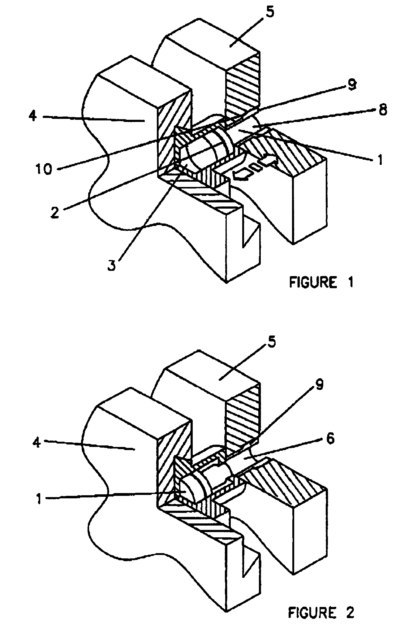
[0143]Referring first to FIG. 1, locking pin 1 is injection moulded from a suitable plastic material and includes a metal strip 2. Locking pin 1 lies in recess 3 between first element 4 and second element 5. Recess 3 has a narrow end 6 which lies within element 5.

[0144]When a magnetic force is applied to locking pin 1, it is caused to move within recess 3 as shown in FIG. 2, so that leg 8 of locking pin 1 is pushed into narrow recess 6, in turn expanding wall 9 so that it locks into the recess 10 provided in element 5.

[0145]Locking pin 1 may be reversed, so that elements 4 and 5 may be released, by the use of magnetic force. Magnetic attraction may be applied for fixing elements 4 and 5 and magnetic repulsion for releasing them, or vice versa. Alternately, the same magnetic force may be applied on opposite sides—for example, on the side near element 4 for fixing and on the side near element 5 for releasing.

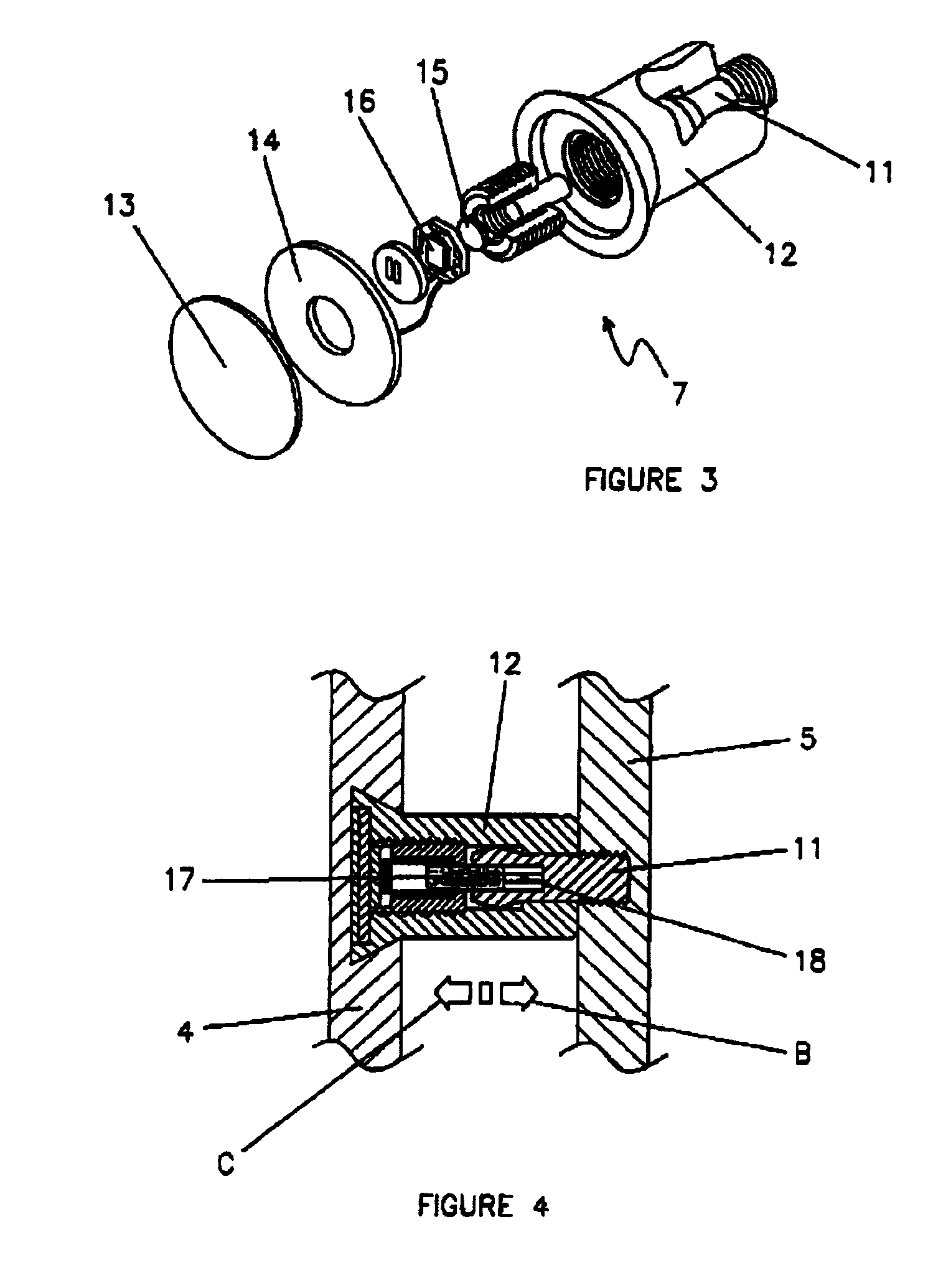
[0146]Turning now to FIG. 3, the connecting means 7 illustrated includes a wa...


PUM


Abstract

A connecting means adapted to fix or release a first element (4) and a second element (5) includes a locking pin (1) which is moveable to remote activation means between a locked position. In which leg (8) expends wall (9) into recess (10), and an unlocked position. The remote activation means may be magnetic, electro-magnetic or any other suitable means. A method of fixing or releasing first and second elements by remote activation means is also disclosed. The invention further provides a first element having first means (166) adapted to cooperate with second means (165) on a second element to facilitate connection of the first and second elements. A method of manufacturing the first element includes the steps of depositing discrete amounts of setable material on a surface of the first element and inverting the element to permit the material to set under the influence of gravity. A method of reducing the spacing between first and second elements by remote activation means is also disclosed.

Description

TECHNICAL FIELD[0001]This invention lies in the field of fixing and / or release systems for a myriad of products and applications. This invention also relates to connectors for use in fixing and release systems.BACKGROUND ART[0002]The need to fix one element to another, such as a panel to a stud, has given rise to a large technology relating to fasteners. Primitive versions, such as nails and screws, are labour intensive and have the drawback that the fixing means are visible externally. It is desirable to fix one element to another so that the fixing means are not visible externally. This desirability may be based on aesthetic or economic reasons. For some applications, it may be desirable that the fixing means are not visible externally, for security purposes.[0003]Common construction practice is to provide a first fixing stage, followed by a “final fix” stage. This is labour intensive and generally results in post-finishing. It is desirable to eliminate the need for the first fixi...

Claims


Application Information

Patent Timeline
Patent Type & Authority Patents(United States)
IPC IPC(8): F16B21/12E04B2/74F16B1/00E04B2/82F16B5/06F16B11/00F16B13/06F16B17/00F16L25/00
CPCE04B2/7457F16B5/065F16B5/0657F16L25/0018F16B5/0664E04B2002/7461E04B2002/7468Y10T403/598Y10S403/01Y10T403/4924Y10T403/593
Inventor RUDDUCK, DICKORY
Owner TELEZYGOLOGY
Why Eureka
Try Eureka