Actuator

a technology of actuators and actuators, applied in the direction of motor/generator/converter stoppers, dynamo-electric converter control, machines/engines, etc., can solve problems such as noise, and achieve the effect of improving the degree of freedom of operation control

Inactive Publication Date: 2007-05-15
MATSUSHITA ELECTRIC WORKS LTD
View PDF26 Cites 28 Cited by
  • Summary
  • Abstract
  • Description
  • Claims
  • Application Information

AI Technical Summary

Benefits of technology

[0006]In an actuator in which a movable member can be moved in two directions of an axial direction and a rotational direction without using a motion direction converting mechanism, an object of the present invention is, with a view to eliminating the above mentioned drawbacks of prior art, to upgrade degree of freedom of operational control of the movable member.

Problems solved by technology

However, when the motion direction converting mechanism converts the motion direction, noises are produced.

Method used


Image

  • Actuator
  • Actuator
  • Actuator

Examples


first embodiment

(First Embodiment)

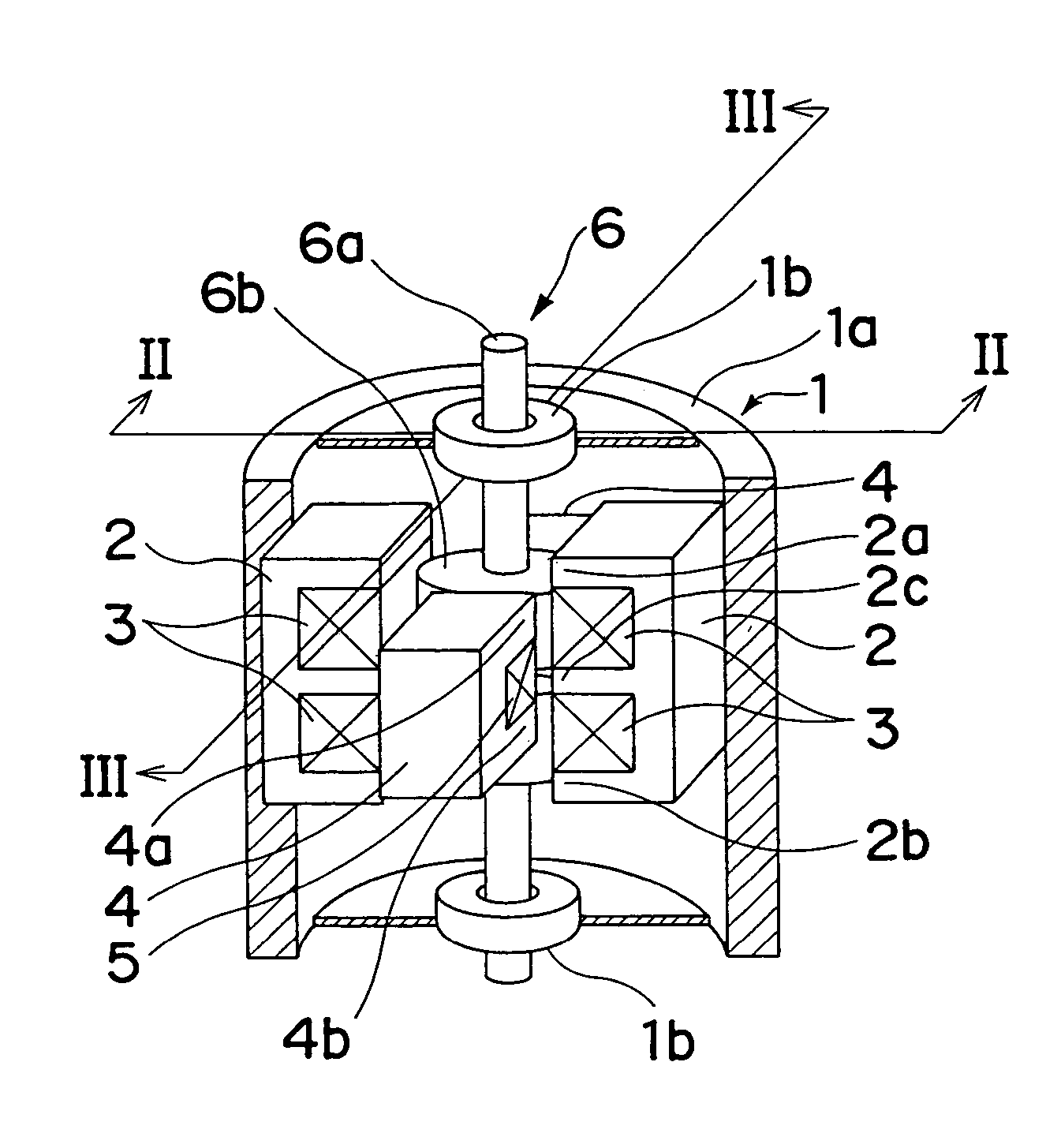
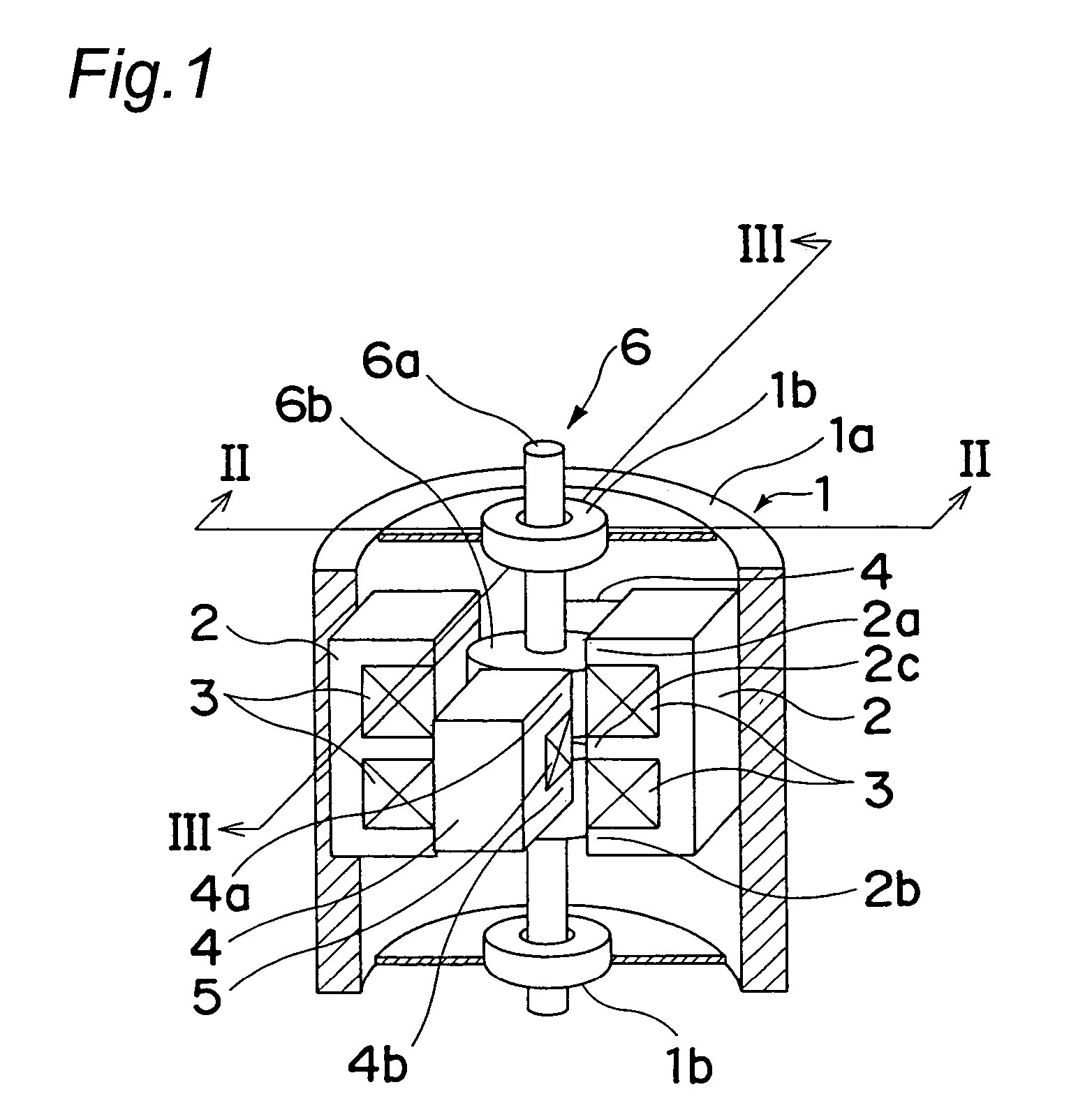
[0040]FIGS. 1 to 10 show an actuator according to a first embodiment of the present invention. As shown in FIG. 1, this actuator mainly includes a casing 1, a pair of first stationary members 2 each having a first coil 3 wound therearound, a pair of second stationary members 4 each having a second coil 5 wound therearound and a movable member 6. The movable member 6 includes a shaft 6a and a driving force generator 6b secured to the shaft 6a.

[0041]The casing 1 includes a housing portion 1a and a pair of bearing portions 1b and accommodates the first and second stationary members 2 and 4 and the movable member 6. The housing portion 1a is formed by metallic magnetic material into a cylindrical shape having a closed bottom. On the other hand, each of the bearing portions 1b is formed by a so-called ball bearing in which metal balls each having a smoothly worked surface are fitted into a cavity of a cylindrical tube having a concentric section. The two bearing portio...

second embodiment

(Second Embodiment)

[0059]Then, FIGS. 11 and 12 show an actuator according to a second embodiment of the present invention. This actuator is different from the actuator of the first embodiment in shapes and relative position of the first stationary member 2 and the second stationary member 4 and other constructions of this actuator are the same as those of the actuator of the first embodiment.

[0060]In this actuator, each of magnetic pole faces of magnetic pole portions of the first stationary member 2 and the second stationary member 4 is formed into a circular curved surface so as to confront the cylindrical magnetic pole face of the driving force generator 6b of the movable member 6 via a predetermined gap. In addition, the magnetic pole portions of the second stationary member 4 are provided in recesses among the E-shaped magnetic pole portions of the first stationary member 2. Thus, when viewed in the axial direction as shown in FIG. 12, each of opposite end portions of the magne...

third embodiment

(Third Embodiment)

[0063]Then, FIG. 13 shows an actuator according to a third embodiment of the present invention. This actuator is different from the actuator of the first embodiment in shape of the movable member 6 and relative position of the movable member 6 and the first stationary member 2 and other constructions of this actuator are the same as those of the actuator of the first embodiment.

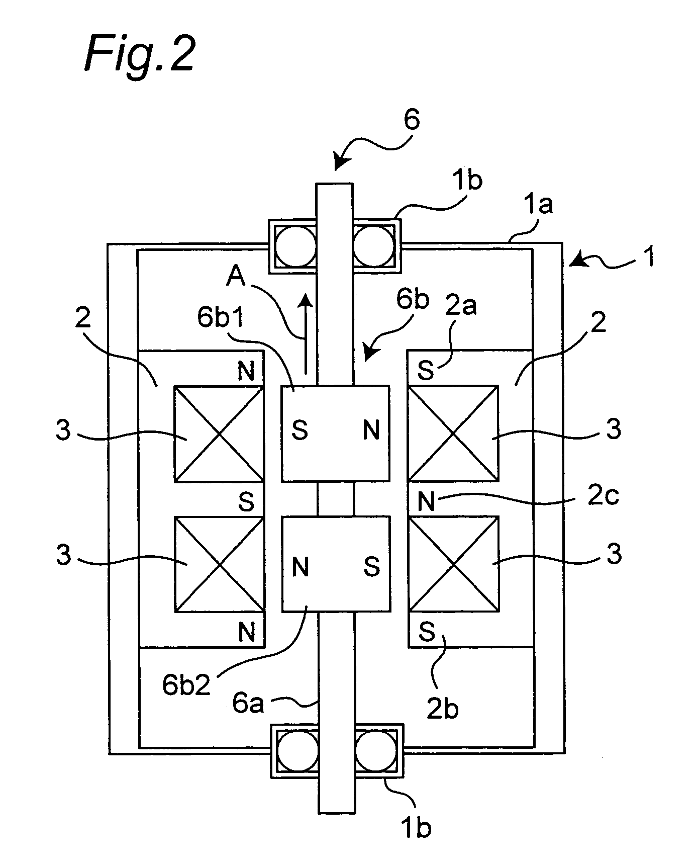
[0064]Each of the magnets 6b1 and 6b2 forming the driving force generator 6b of the movable member 6 is a cylindrical magnet having a thickness smaller than an axial width of the recesses among the E-shaped magnetic pole portions 2a to 2c of the first stationary member 2 and a diameter of the cylindrical magnet is formed larger than a distance between the corresponding magnetic pole portions of a pair of the first stationary members 2 such that the cylindrical magnet projects into each of the recesses among the magnetic pole portions 2a to 2c of the first stationary member 2. Hence, motion o...


PUM


Abstract

An actuator includes a casing, a stationary member having a coil member and mounted in the casing and a movable member having a moving element and supported by the casing. The moving element has a shaft and is supported by the casing so as to be moved in an axial direction of the shaft and in a rotational direction having the axial direction of the shaft as its rotational axis and the moving element is moved in the axial direction and in the rotational direction by causing electric current to flow through the coil member. The stationary member includes a first stationary member for imparting to the movable member a force oriented in the axial direction and a second stationary member for imparting to the movable member a force oriented in the rotational direction, while the coil member includes a first coil member for exciting a first magnetic path passing through the first stationary member and a second coil member for exciting a second magnetic path passing through the second stationary member.

Description

TECHNICAL FIELD[0001]The present invention relates an actuator which is capable of moving in two directions of an axial direction and a rotational direction.BACKGROUND ART[0002]Many actuators are adapted to move in one direction of a linear direction or a rotational direction. When an actuator is moved in two directions of the linear direction and the rotational direction, a motion direction converting mechanism for converting a motion direction mechanically is employed. However, when the motion direction converting mechanism converts the motion direction, noises are produced.[0003]In a linear actuator in which a movable member (plunger) having a shaft is disposed inside a stationary member (yoke) so as to have a gap with the stationary member and a magnetic path is excited by a coil such that the movable member is moved in an axial direction of the shaft, Japanese Patent Laid-Open Publication No. 2002-78310 discloses an arrangement in which by making the gap nonuniform relative to ...

Claims


Application Information

Patent Timeline
Patent Type & Authority Patents(United States)
IPC IPC(8): H02K33/00H02K33/16
CPCH02K33/16H02K2201/18
Inventor HASEGAWA, YUYAHIRATA, KATSUHIROMITSUTAKE, YOSHIOOTA, TOMOHIROMOTOHASHI, RYOKUNITA, TOMOHIROSHIMIZU, HIROAKIYABUUCHI, HIDEKAZUNISHINAKA, TAKAHIRO
Owner MATSUSHITA ELECTRIC WORKS LTD
Why Eureka
Try Eureka