Magnetic resonance system and operating method for RF pulse optimization

a magnetic resonance system and optimization method technology, applied in the field of magnetic resonance system operation, can solve the problems of inhomogeneous penetration behavior of rf pulses, inability to optimize rf pulses, and inability to accurately measure, etc., and achieve the effect of better optimization of rf pulses

Active Publication Date: 2007-05-15
SIEMENS HEALTHCARE GMBH
View PDF15 Cites 39 Cited by
  • Summary
  • Abstract
  • Description
  • Claims
  • Application Information

AI Technical Summary

Benefits of technology

[0010]An object of the present invention to provide a method for operation of a magnetic resonance system and a magnetic resonance system, with which a better optimization of the RF pulses with regard to the homogeneity of the B1 field can be achieved.

Problems solved by technology

Spatial fluctuations in the field strength of the excited B1 field therefore lead to unwanted variations in the received magnetic resonance signal that can adulterate the measurement result.
For high magnetic field strengths—that are inevitable given due necessary magnetic basic field B0 in a magnetic resonance tomography scanner—the RF pulses disadvantageously exhibit an inhomogeneous penetration behavior in conductive and dielectric media such as, for example, tissue.
Since, however, in a magnetic scan, every RF pulse acts in general in a different manner both with regard to its function and with regard to the relevant volumes, this optimization strategy is too restrictive.

Method used


Image

  • Magnetic resonance system and operating method for RF pulse optimization
  • Magnetic resonance system and operating method for RF pulse optimization
  • Magnetic resonance system and operating method for RF pulse optimization

Examples


Embodiment Construction

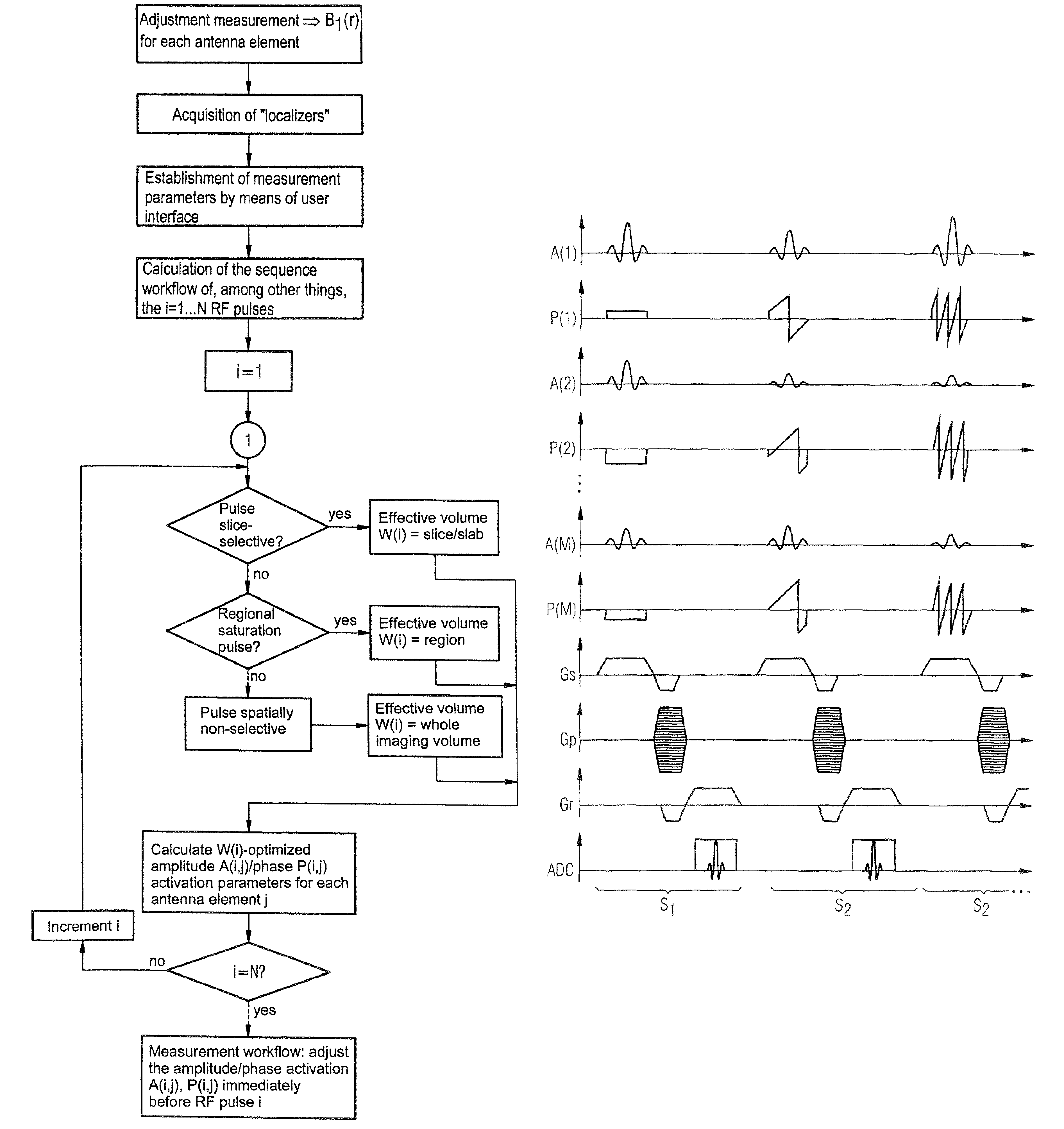
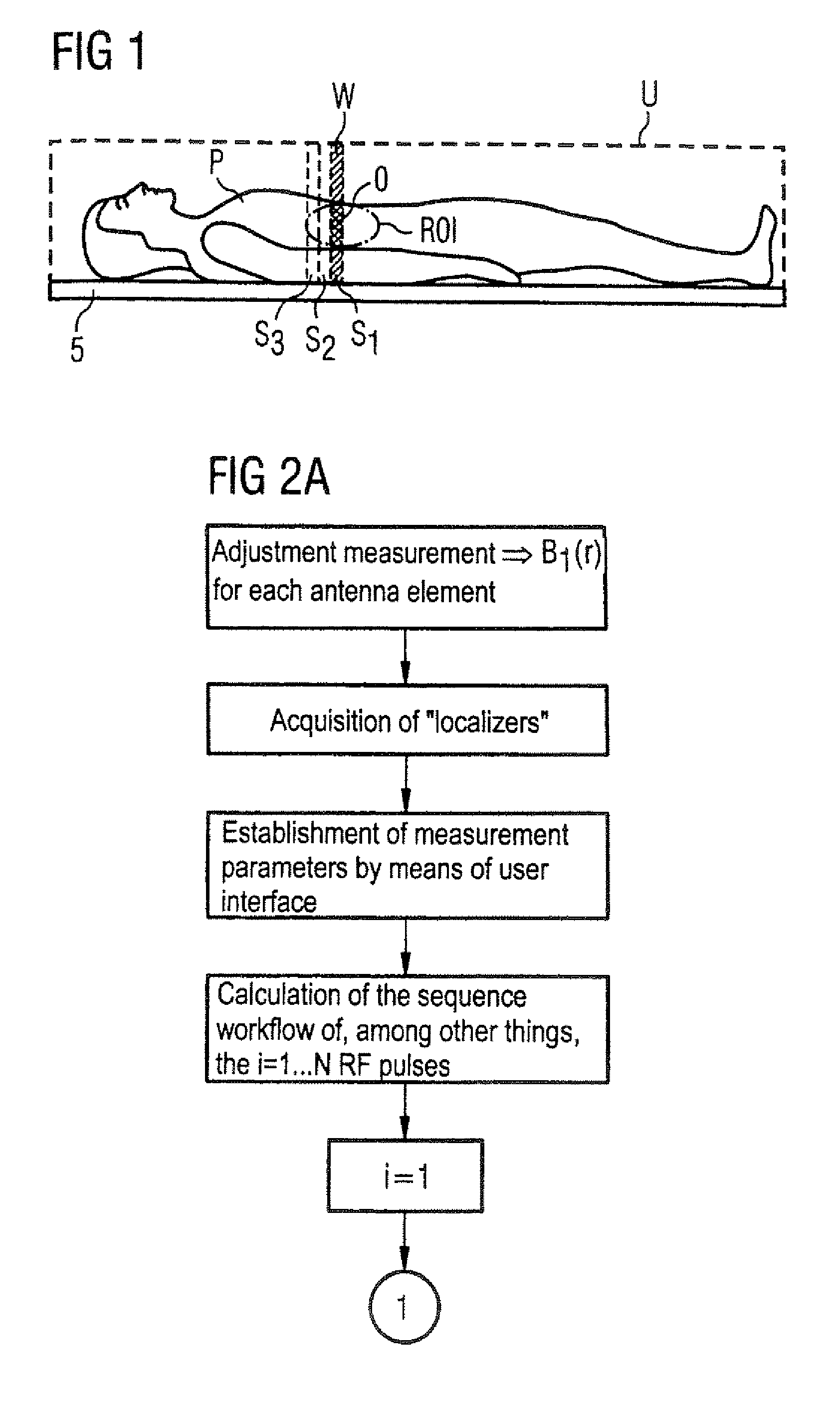
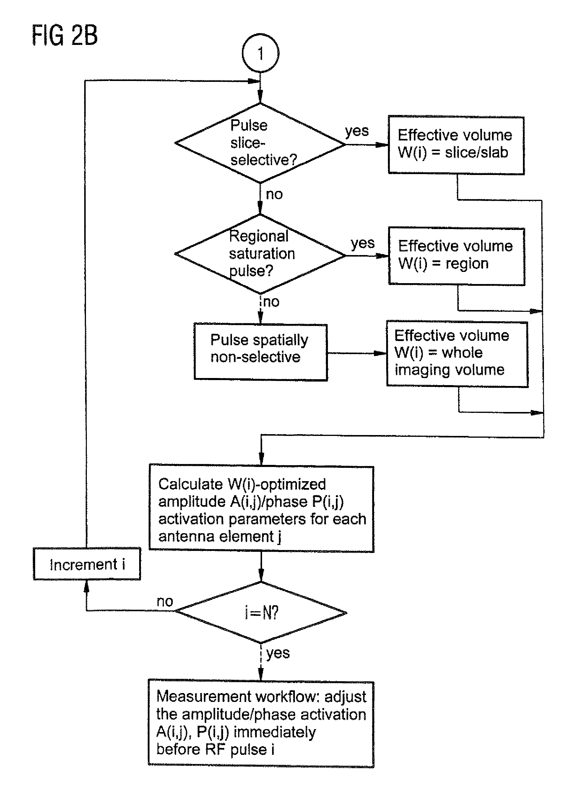
[0038]A patient P lying on a patient bed 5 within an examination volume U of the magnetic resonance system is shown in FIG. 1. In the MR examination, exposures (scans) are generated in various slices S, S1, S2, S3 perpendicular to the longitudinal axis of the patient P. For clarity, here only three slices S1, S2, S3 are shown, significantly enlarged. The optimization of the radiated RF pulses inventively ensues, for each individual RF pulse, with regard to the slice in which the appertaining RF pulse should act. As an example, in FIG. 1 the slice S1 is determined as an effective volume W, with regard to which an optimal homogenization of the RF pulse radiated for excitation of the appertaining slice S1 should ensue.

[0039]Additionally, in FIG. 1 the possibility of an operator of the MR system determining a “region of interest” ROI is schematically shown. In this case, the optimization of the RF pulse optionally ensues predominantly with regard to the slice quantity made up of effecti...


PUM


Abstract

In a magnetic resonance system and an operating method therefor, a B1 field distribution of a radio-frequency antenna is measured in at least one part of a examination volume of the magnetic resonance system, and then the RF pulses emitted by the radio-frequency antenna are optimized, based on the determined B1 field distribution, for homogenization in a specific volume. An effective volume within the examination volume is determined beforehand for each applied RF pulse and, based on the determined B1 field distribution, the appertaining RF pulse is individually adjusted such that the B1 field is homogenized within the effective volume of the RF pulse.

Description

BACKGROUND OF THE INVENTION[0001]1. Field of the Invention[0002]The invention concerns a method for operation of a magnetic resonance system of the type wherein, in which a B1 field distribution of the radio-frequency pulses (“RF pulses”) radiated into an examination volume by a radio-frequency antenna of the magnetic resonance examination system is determined, and then the RF pulses emitted by the radio-frequency antenna are optimized, based on the determined B1 field distribution, for homogenization in a specific volume. Moreover, the invention concerns a magnetic resonance system of the type having a radio-frequency antenna for emission of RF pulses into an examination volume, with a measuring unit to measure a B1 field distribution of the RF pulses radiated into the examination volume by the radio-frequency antenna, and with a control device which, based on the determined B1 field distribution, optimizes the RF pulses emitted by the radio-frequency antenna for homogenization in ...

Claims


Application Information

Patent Timeline
Patent Type & Authority Patents(United States)
IPC IPC(8): G01V3/00A61B5/055G01R33/34G01R33/3415G01R33/36
CPCG01R33/543G01R33/5612G01R33/246G01R33/5659
Inventor FEIWEIER, THORSTENLADEBECK, RALFOPPELT, RALPHRENZ, WOLFGANGVESTER, MARKUS
Owner SIEMENS HEALTHCARE GMBH
Why Eureka
Try Eureka