
Passive repeater/terminator

Inactive Publication Date: 2007-05-15
THE BOEING CO
View PDF2 Cites 2 Cited by
  • Summary
  • Abstract
  • Description
  • Claims
  • Application Information

AI Technical Summary

Benefits of technology

[0007]The present invention provides a passive terminator between a plurality of nodes. Advantageously, embodiments of the present invention passively match impedance between the plurality of the nodes and passively set an operating differential voltage level according to a standard that may be used as desired. As a result, the present invention provides a passive terminator that is simple, inexpensive, compact, and that does not consume processing resources that are consumed by active terminators or require an external power supply.

Problems solved by technology

However, active repeater / terminators include relatively complex, active electronic circuitry.
A level of active arbitration is required for mitigation of data path selection, thereby adding further complexity to the active repeater / terminator.
However, drive capability is limited and external power is required.
Both of these commercially-available active repeater / terminators have a relatively large size, generate heat, and consume processing resources.
As a result, both of these active repeater / terminators are complex, suffer from reliability concerns, and are relatively expensive.
However, there is an unmet need in the art for a passive repeater / terminator.

Method used


Image

  • Passive repeater/terminator
  • Passive repeater/terminator
  • Passive repeater/terminator

Examples


Embodiment Construction

[0015]By way of overview, the present invention provides a passive terminator between a plurality of nodes. Advantageously, embodiments of the present invention passively match impedance between the plurality of the nodes and passively set an operating differential voltage level according to a standard that may be used. As a result, the present invention provides a passive terminator that is simple, inexpensive, compact, and that does not consume processing resources that are consumed by active terminators.

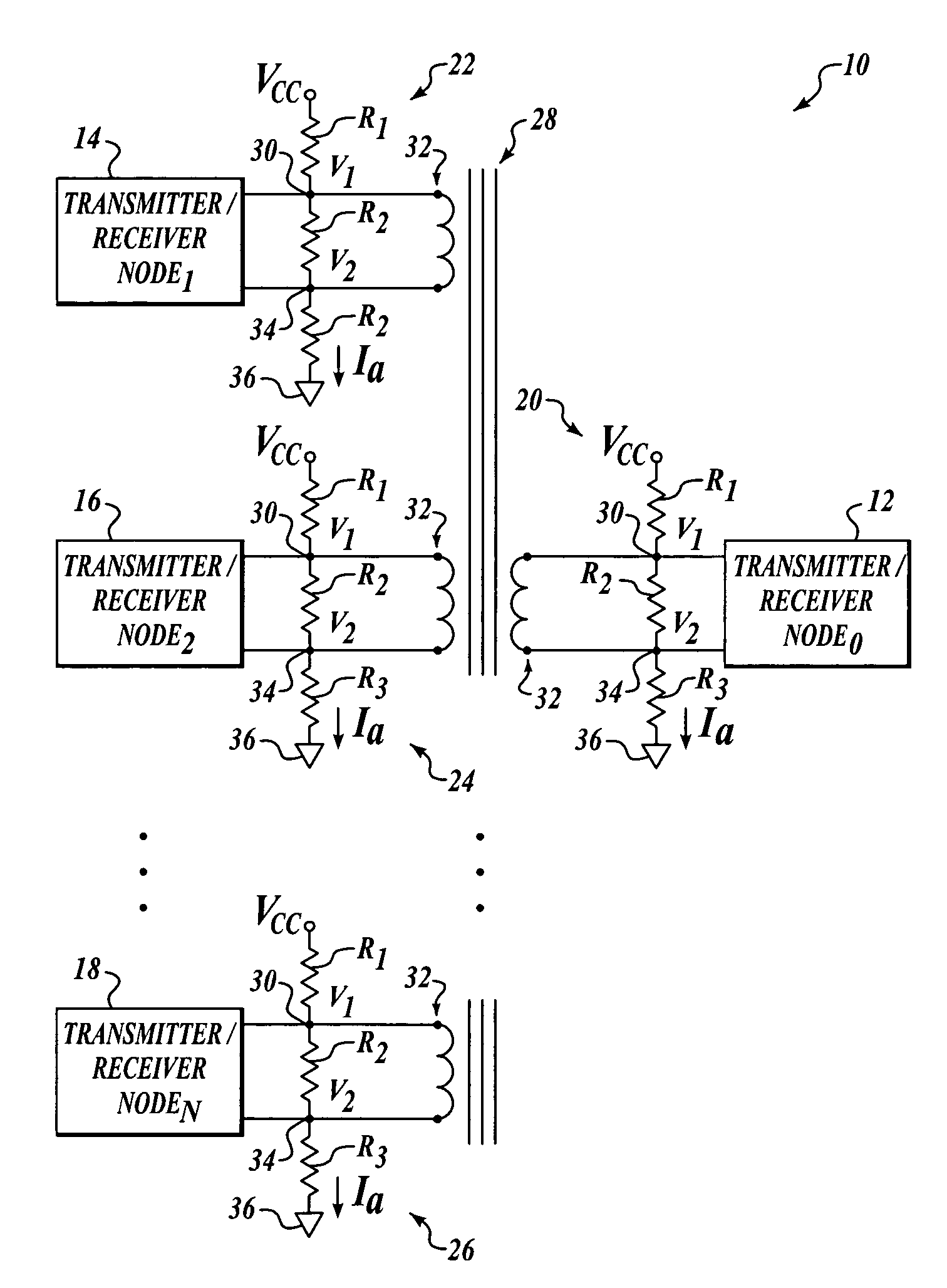
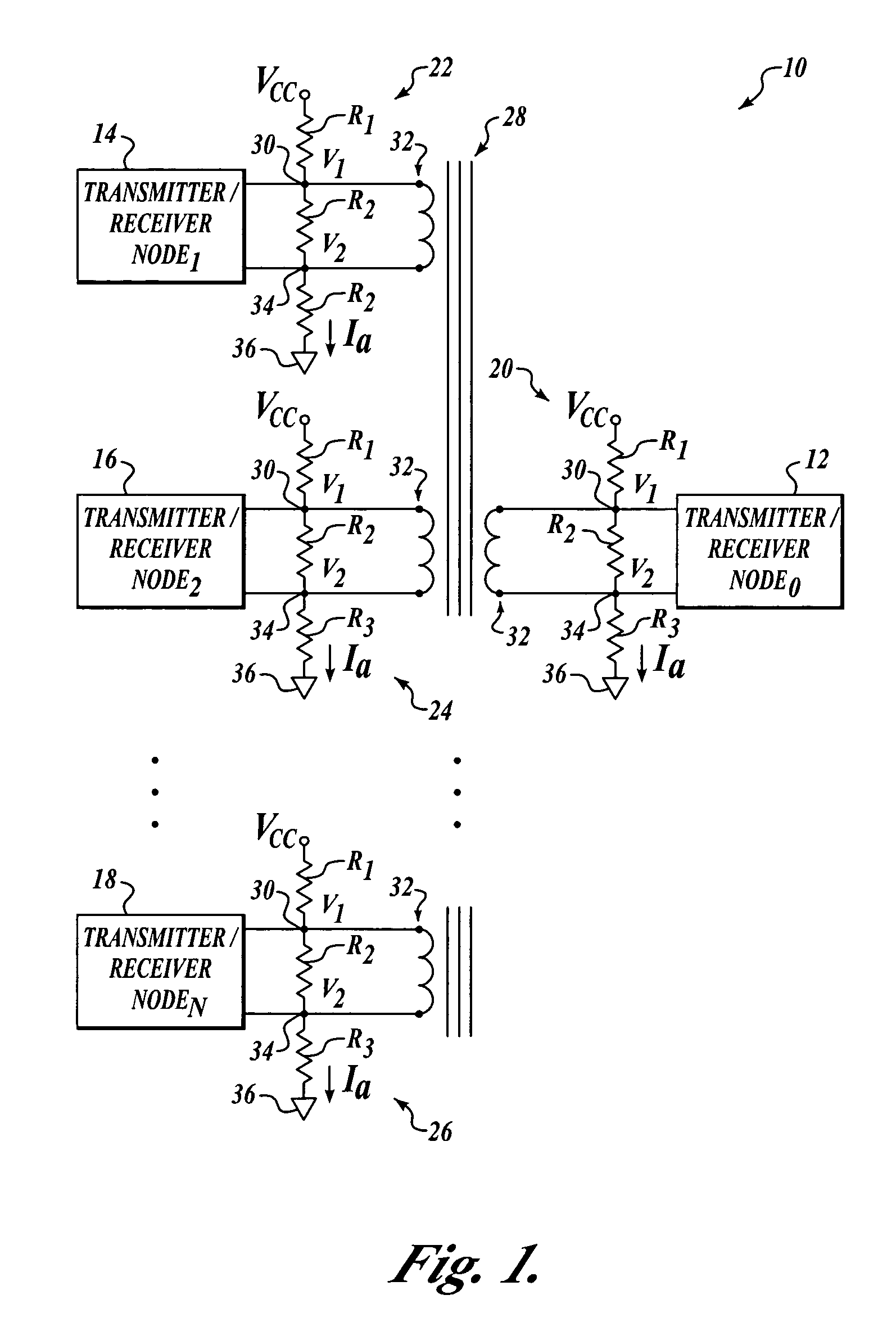
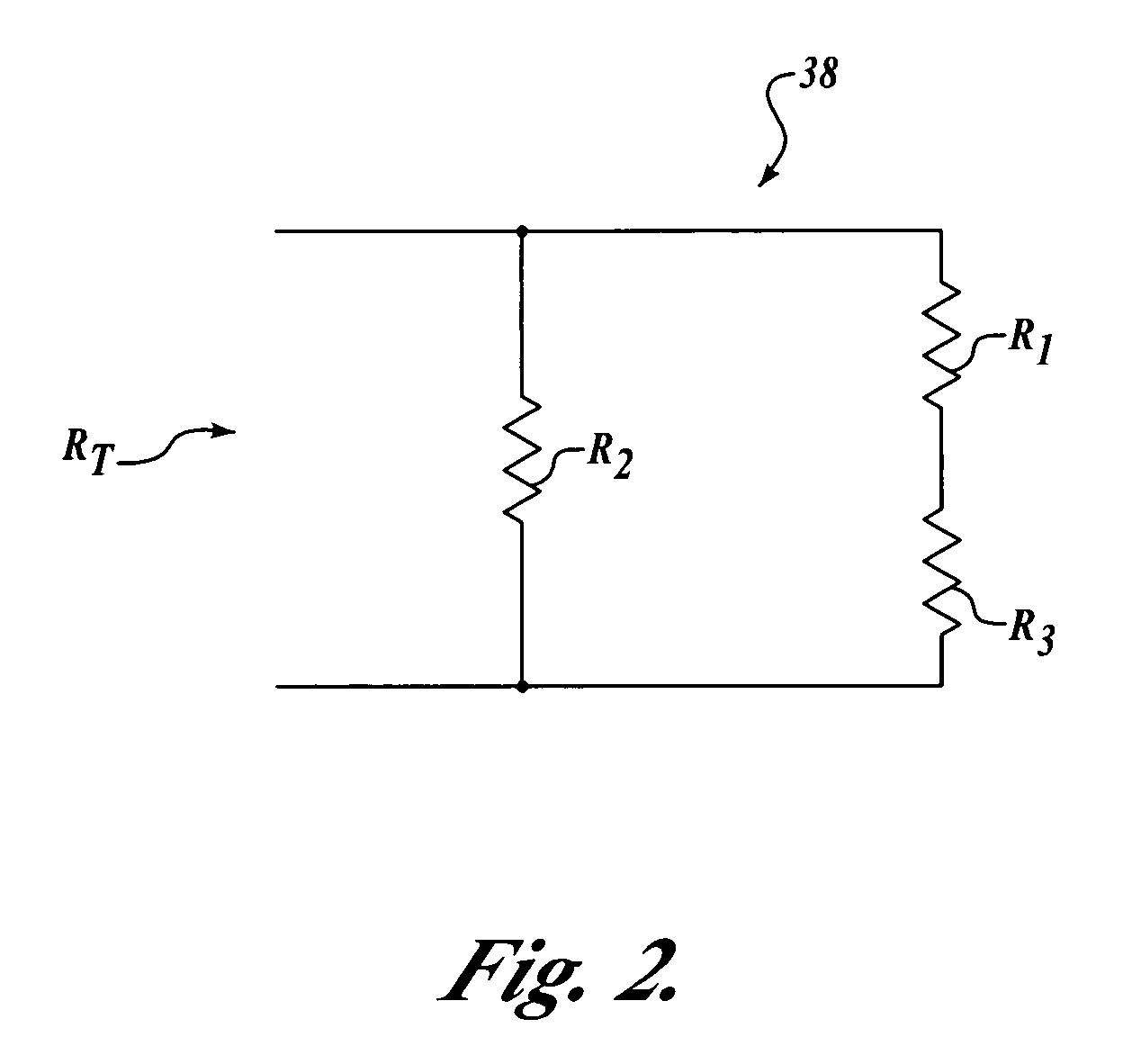
[0016]Referring now to FIG. 1 and by way of introduction, according to an exemplary embodiment of the present invention, a passive terminator 10 between a plurality of nodes 12, 14, 16, and 18 includes a voltage divider 20 that is configured to passively set a differential voltage level between a first voltage level V1 and a second voltage level V2. The voltage divider 20 has a Thevenin resistance RT and is electrically connectable to the node 12. Voltage dividers 22, 24, and 26 a...


PUM


Abstract

A passive terminator between a plurality of nodes includes a first voltage divider configured to passively set a differential voltage level between a first voltage level and a second voltage level. The first voltage divider has a Thevenin resistance and is electrically connectable to a first node. At least a second voltage divider is configured to passively set the differential voltage level between the first voltage level and the second voltage level. The second voltage divider has the Thevenin resistance and is electrically connectable to at least a second node. A transformer is electrically connected between the first voltage divider and the at least second voltage divider. The transformer has a reactance that is substantially greater than the Thevenin resistance of the first voltage divider and the at least second voltage divider.

Description

GOVERNMENT LICENSE RIGHTS[0001]This invention was made with Government support under U.S. Government contract N00024-00-C-6103 awarded by the U.S. Navy. The Government has certain rights in this invention.FIELD OF THE INVENTION[0002]The present invention relates generally to electrical interfaces and, more specifically, to passive electrical interfaces.BACKGROUND OF THE INVENTION[0003]Two-way serial communications in electrical systems are accomplished, in part, with electrical interfaces between nodes. For example, a controller area network or carrier area-wide network (both hereinafter referred to as “CAN”) provides two-way serial communications via electrically-conductive wire according to CAN standard ISO 11898-2. The communications are provided between CAN transmitter receiver nodes. Electrical interfaces, such as repeaters and / or terminators, are provided between the nodes to match impedance and provide operating voltage levels that comply with the CAN standard.[0004]In some a...

Claims


Application Information

Patent Timeline
IPC IPC(8): H04B7/185H04B1/38H04B3/36H04L25/02H04M1/00
CPCH04B3/36H04L25/0298
Inventor BEIERLE, ROBERT T.
Owner THE BOEING CO
Learn More