
System and method for light-based guidance of autonomous vehicles

a technology for autonomous vehicles and light-based guidance, applied in the field of methods and, can solve the problems of insufficient accuracy of satellite positioning systems to provide effective, accurate and safe motion of uavs, theoretical limit of position accuracy, and insufficient to navigate safely towards uavs, etc., to achieve low power consumption, simple, inexpensive and compact light-emitting infrastructure, and quick, efficient and safe manner

Inactive Publication Date: 2021-09-30
DELGADO EDGAR EMILIO MORALES
View PDF7 Cites 0 Cited by
  • Summary
  • Abstract
  • Description
  • Claims
  • Application Information

AI Technical Summary

Benefits of technology

The invention is a new guidance system for autonomous vehicles that allows them to travel with precision, even in places without satellite-based navigation or in poor weather conditions. It uses a simple and inexpensive infrastructure, making it suitable for all types of autonomous vehicles. The system uses emitted light signals to transmit information and enable cryptographic authentication, ensuring safety against malicious attacks. This invention can lead to new forms of transportation and delivery, making it a useful and secure tool for autonomous vehicles.

Problems solved by technology

However, in the case of maneuvers involving close proximity between autonomous vehicles, proximity to other objects or in aircraft maneuvers such as approaching, take-off and landing, the accuracy of satellite positioning systems is not enough to provide effective, accurate and safe motion of UAVs.
In the case of satellite-based navigation systems (for example, U.S. Pat. No. 3,789,409A), there is a theoretical limit to the position accuracy (4 meters RMS lateral accuracy for GPS under direct line of sight), which in some cases is not enough to navigate safely an UAV towards a mobile, ground station or for entering a warehouse.
Moreover, since satellite navigation systems are based on measuring the different time of arrival of the radio waves emitted from the satellites, the position accuracy decreases dramatically in the presence of obstacles that produce multi-path reflection of such radio waves, resulting in significant position and orientation errors that restricts navigation of the autonomous vehicle.
Furthermore, satellite-based navigation becomes impossible in situations without direct line of sight towards GPS satellites, in planets without GPS satellite infrastructure or in GPS denied environments such as the interior of a warehouse, inside building, in tunnels or underwater.
However, they operate with a finite sampling rate, which produces linear accumulation of acceleration errors over time, resulting in a quadratic and cubic error in velocity and position, respectively.
Additionally, they are very sensitive to electromagnetic and magnetic interference, producing significant errors when used near power-lines or near objects with magnets or ferromagnetic materials and require frequent adjustment using a satellite navigation system, which is not accessible in indoors environments.
However, these systems require a very bulky, expensive, and power consuming infrastructure, restricting their usage to airports and guidance of large aircrafts.
Furthermore, the on-board receiver is heavy, bulky, and require relatively large antennas, restricting their integration in small UAVs.
However, their implementation require high resolution on-board cameras and complex images processing algorithms which operate with a high power consumption.
Another disadvantage is that such visual markers cannot be seen in fog, heavy rain, low light conditions or at large distances due to the finite camera resolution.
Additionally, they are not secure and cannot be cryptographically authenticated.

Method used


Image

  • System and method for light-based guidance of autonomous vehicles
  • System and method for light-based guidance of autonomous vehicles
  • System and method for light-based guidance of autonomous vehicles

Examples


Embodiment Construction

[0019]Embodiments of systems, devices and methods for light-based guidance of autonomous vehicles are described herein. In the following description, numerous specific details are set forth to provide a thorough understanding of the embodiments. One skilled in the relevant art will recognize, however, that the techniques described herein can be practiced without one or more of the specific details, or with other methods, components, materials, etc. In other instances, well-know structures, materials or operations are not shown or describe in detail to avoid obscuring certain aspects.

[0020]The content of this disclosure may be applied to multiple fields, such as navigation, autonomous vehicles, aerial vehicles, marine navigation, aerospace navigation, spacecrafts docking, and satellites.

[0021]Reference throughout this specification to “one embodiment”, “an embodiment”, or “some embodiments” means that a particular feature, structure, or characteristic described may be included in at ...


PUM


Abstract

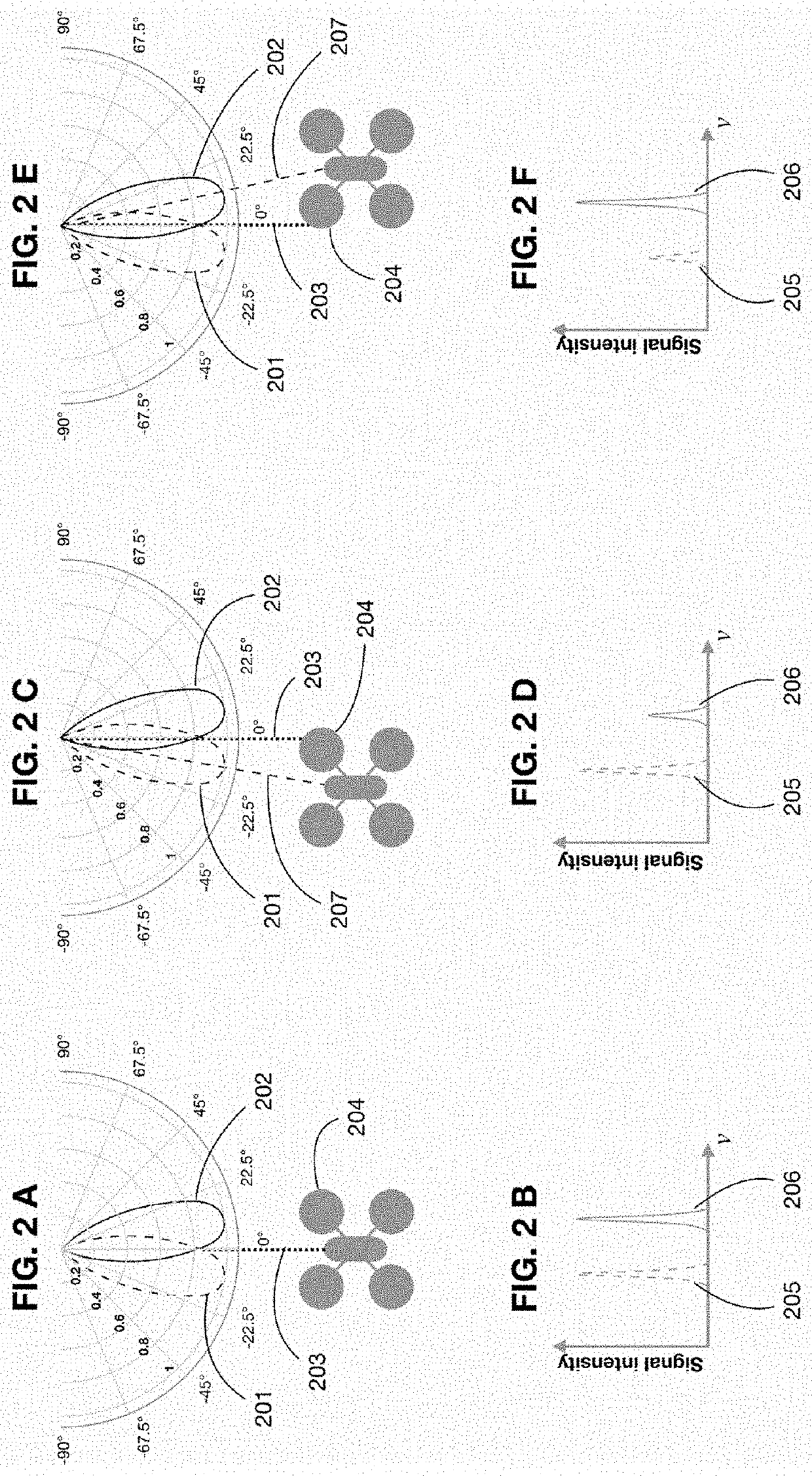
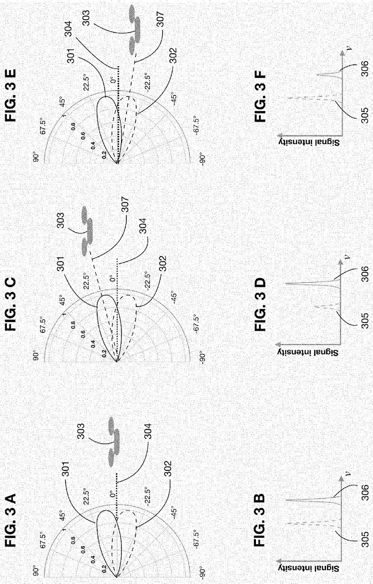
A method for providing guidance to autonomous vehicles comprising emitting light signals from a plurality of light sources, wherein each light source emits a light signal with an angular dependent intensity profile, detecting the plurality of emitted light signals with an on-board light detector, processing the plurality of light signals detected by the light detector to distinguish each one of the detected light signals, comparing the distinguished detected light signals, using the distinguished detected light signals to encounter the orientation of the on-board light detector relative to the light sources, generating a control signal from the distinguished detected light signal and using the control signal to provide navigation guidance to the autonomous vehicle.

Description

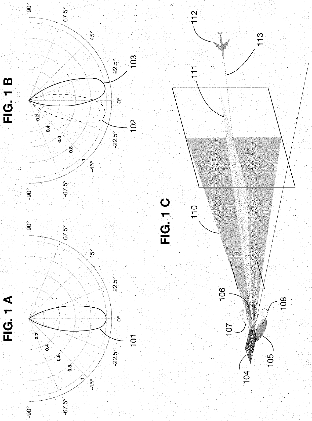
BACKGROUND[0001]The present invention relates to methods and systems for providing navigation guidance to autonomous vehicles. In particular, the present invention is related, but not restricted, to light-based guidance of autonomous vehicles, light-based guidance of unmanned areal vehicles and optical guidance systems.[0002]Conventional navigation and guidance of autonomous vehicles such as ground vehicles or unmanned aerial vehicles (UAVs) use satellite positioning systems like the global positioning system (GPS) in conjunction with on-board inertial measurement units (IMUs) to calculate the absolute position and orientation of unmanned vehicles on earth or the position and orientation of unmanned vehicles relative to objects, to other vehicles or to mobile and ground stations. This conjunction is very effective in cruising maneuvers in a three-dimensional environment where the unmanned vehicles are widely spaced and far from any obstacle. However, in the case of maneuvers involvi...

Claims


Application Information

Patent Timeline
Patent Type & Authority Applications(United States)
IPC IPC(8): G05D1/08G05D1/00G05D1/10G05D1/04B64C39/02
CPCG05D1/0808G05D1/0088G05D1/101G05D1/0206B64C39/024B64C2201/141G05D1/042G05D1/0676G05D1/104G08G5/0026G08G5/0021G08G5/0065G08G5/025G08G5/0069B64D45/08B64F1/18G01S1/7032G01S5/163G01S5/16B64U2201/102B64U2201/104B64U2201/10B64U70/95B64F1/20B64U2201/20
Inventor DELGADO, EDGAR EMILIO MORALES
Owner DELGADO EDGAR EMILIO MORALES
Learn More