Coordinated lift system with user selectable RF channels

a lift system and user-selectable technology, applied in the direction of lifts, lifting devices, instruments, etc., can solve the problems of hazard to people working near, damage to connecting lines, and relatively expensive built-in units

Active Publication Date: 2007-05-22
GRAY MFG
View PDF80 Cites 71 Cited by
  • Summary
  • Abstract
  • Description
  • Claims
  • Application Information

AI Technical Summary

Benefits of technology

[0011]Each of the lift mechanisms preferably includes surface engaging wheels and a tongue or handle which enable the lift mechanisms to be moved manually to the required location. Each lift mechanism may also include carriage adapters to expand the range of vehicle wheels which the carriage may usefully engage. Alternatively, other carriage adapters may be provided for lifting structures other than vehicles, such as aircraft, shipping containers, housing construction subassemblies, and the like.

Problems solved by technology

However, built-in units tend to be relatively expensive and are sometimes not as useful as they might otherwise be due to their immobility.
The presence of the wires and lines in the work area poses a hazard to people working near the vehicle, and the connecting lines may be damaged by vehicles driving over them.
However, the wireless system of '461 does not allow the user to select the frequency of operation of transceivers of the control units of the lift devices.
For this reason, two systems may not be usable simultaneously in a given location without the possibility of interference.
Further, if signal interference occurs at a specific location, the frequency on which the system is operating cannot be changed in the field to avoid such interference.

Method used


Image

  • Coordinated lift system with user selectable RF channels
  • Coordinated lift system with user selectable RF channels
  • Coordinated lift system with user selectable RF channels

Examples


Embodiment Construction

[0021]As required, detailed embodiments of the present invention are disclosed herein; however, it is to be understood that the disclosed embodiments are merely exemplary of the invention, which may be embodied in various forms. Therefore, specific structural and functional details disclosed herein are not to be interpreted as limiting, but merely as a basis for the claims and as a representative basis for teaching one skilled in the art to variously employ the present invention in virtually any appropriately detailed structure.

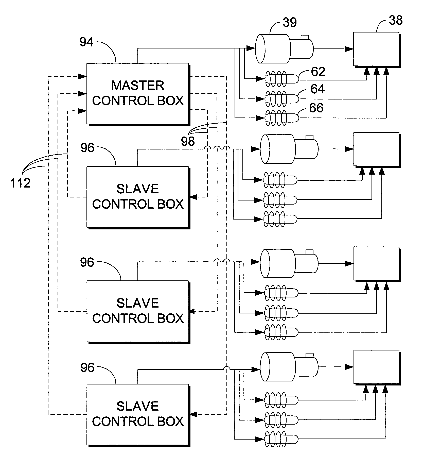
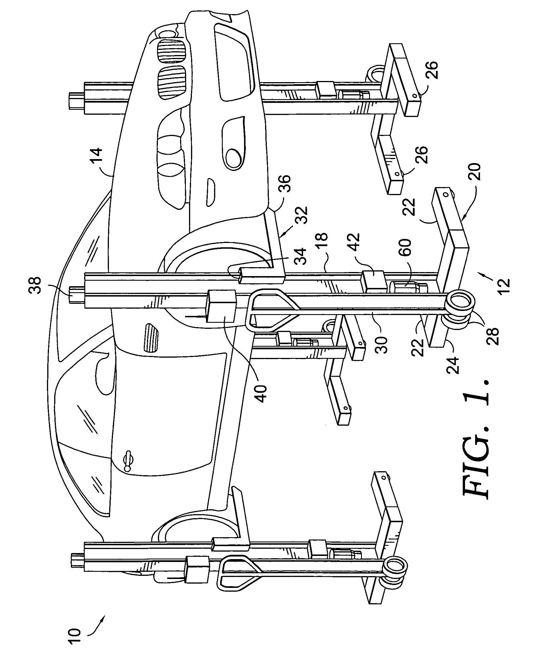
[0022]Referring now to the drawings in detail, and initially to FIG. 1, numeral 10 generally designates a coordinated lift system with user selectable RF channels which embodies the present invention. Generally, the lift system 10 includes four lift mechanisms, or mobile column lifts (MCL's), 12 that communicate by wireless signals to coordinate the movement of a vehicle 14 relative to a surface, such as pavement, a garage floor, or the like. It should be und...


PUM


Abstract

A coordinated lift system with user selectable RF channels coordinates the raising and lowering of a vehicle relative to a surface by using wireless communications. The lift system includes at least two lift mechanisms each having support frame, including a post, a carriage, an actuating device, and a control device with a channel selector switch. The carriage is slidably mounted on the post and is configured to support a portion of the vehicle. The actuating device is engaged between the support frame and the carriage and is activated to move the carriage relative to the post. The control device is interfaced with the actuating device and includes an RF transceiver to enable communication by RF signals with the other control device. The channel on which the transceiver operates is user selectable in the field. A rechargeable battery may provide power to the control device to allow for increased mobility of the lift system.

Description

CROSS-REFERENCE TO RELATED APPLICATION[0001]This application claims priority under 35 U.S.C. 119(e) and 37 C.F.R. 1.78(a)(4) based upon copending U.S. Provisional Application Ser. No. 60 / 491,953 for COORDINATED LIFT SYSTEM WITH SELECTABLE RF CHANNELS, filed Aug. 1, 2003.BACKGROUND OF THE INVENTION[0002]The present invention relates to a coordinated lift system and, more particularly, to a coordinated lift system incorporating at least two lift mechanisms that communicate by wireless signals on user selected RF channels to coordinate lift mechanisms in the raising and lowering of a vehicle.[0003]The need to lift a vehicle from the ground for service work is well established. For instance, it is often necessary to lift a vehicle for tire rotation or replacement, steering alignment, oil changes, brake inspections, exhaust work, and other automotive maintenance. Traditionally, lifting a vehicle has been accomplished through the use of equipment that is built-in to the service facility, ...

Claims


Application Information

Patent Timeline
Patent Type & Authority Patents(United States)
IPC IPC(8): B66F7/16B66F9/04B66F3/46
CPCB66F3/46
Inventor BAKER, WILLIAM J.
Owner GRAY MFG
Why Eureka
Try Eureka