Electromagnetic valve apparatus

a technology of electromagnetic valves and valve bodies, applied in the direction of valve operating means/release devices, machines/engines, magnetic bodies, etc., can solve the problems of limited ability to reduce initial gaps, small size, and difficulty in providing electromagnetic valve apparatuses, and achieve the effect of alleviating boun

Active Publication Date: 2007-05-22
MITSUBISHI HEAVY IND ENGINE & TURBOCHARGER LTD
View PDF9 Cites 4 Cited by
  • Summary
  • Abstract
  • Description
  • Claims
  • Application Information

AI Technical Summary

Benefits of technology

[0011]To prevent this, it is necessary to provide a sufficient gap between the surfaces. According to the present invention, the gap between the surfaces is smaller in the central part than in the peripheral part of the surfaces because the surface of the armature is shaped into a convexly curved surface. Therefore, even if the armature is installed inclined by the same angle that may happen in the prior art, interference of the armature and core does not occur. This means that the gap between the surfaces in the central part can be decreased without the occurrence of interference when it happens that the armature is installed aslant caused by insufficient accuracy. Accordingly, it is possible to compose the valve apparatus so that the electromagnetic attraction is increased compared to the prior art.
[0013]Next, the second object of the present invention can be attained by at least one passage hole being provided in the armature, the passage hole having a tapered portion broadening toward the surface of the core facing to the surface of the armature. With this composition of the armature, when the armature is attracted toward the core and the valve connected to the armature closes the high-pressure fuel passage, the fuel rapidly compressed in the gap between the surfaces of the core and armature can escape through the passage hole. The occurrence of bouncing-when-closing of the valve connected to the armature and supported by a spring, is prevented or the bouncing alleviated.
[0014]When the electromagnetic attraction is released and the armature is drawn back from the core side by the spring together with the valve connected to the armature to open the valve, the bouncing-when-opening of the valve has a harder time occurring when there is some resistance for the valve to move back. When the passage hole is of constant cross-sectional area, although the occurrence of valve bouncing-when-closing can be suppressed, the occurrence of valve bouncing-when-opening is rather conduced. By making the passage of fuel through the passage hole easier when closing the valve than when opening the valve by forming each passage hole to have a tapered portion broadening toward the surface of the core, the occurrence of valve bouncing-when-closing is prevented or suppressed without excessively conducing the occurrence of valve bouncing-when-opening.
[0016]In this case, the fuel compressed in the gap between the surfaces of the core and armature by rapid attraction of the armature toward the core bends the thin plate located remotest from the surface of the armature to escape through the passage hole, as a result of which the occurrence of valve bouncing-when-closing is prevented or suppressed. When the armature is drawn back from the surface of the core side to open the valve, the fuel below the armature does not pass through the passage hole because the passage hole is closed by the thin plate located remotest from the surface of the armature. Therefore, the occurrence of valve bouncing-when-opening is not conduced. Further, eddy current loss is decreased by composing the armature of piled thin plates.

Problems solved by technology

Therefore, there has been a limit to the ability to decrease the initial gap in order to increase the electromagnetic attraction.
It has thus been difficult to provide an electromagnetic valve apparatus which is small in size and can exert strong electromagnetic attraction.
Further, there has been a problem of the occurrence of bouncing-when-closing of the valve body connected to the armature when the armature is attracted toward the core to allow the valve body to close the fuel passage and a problem of occurrence of bouncing-when-opening of the valve body when the valve body is allowed to open the fuel passage.
It may happen that the periphery of the surface of the armature contacts the surface of the core, that is, interference of the surfaces of the armature and core occurs before the valve seats on the valve seat when the armature is attracted toward the core, which results in an incomplete closing of the valve.
This can happen in the case where the surfaces of the core and armature facing each other are flat surfaces or curved surfaces facing with the same gap allover the surfaces, if the armature is installed such that the center axis of the armature is inclined to the center axis of the core caused by insufficient accuracy of component parts.

Method used


Image

  • Electromagnetic valve apparatus
  • Electromagnetic valve apparatus
  • Electromagnetic valve apparatus

Examples


sixth embodiment

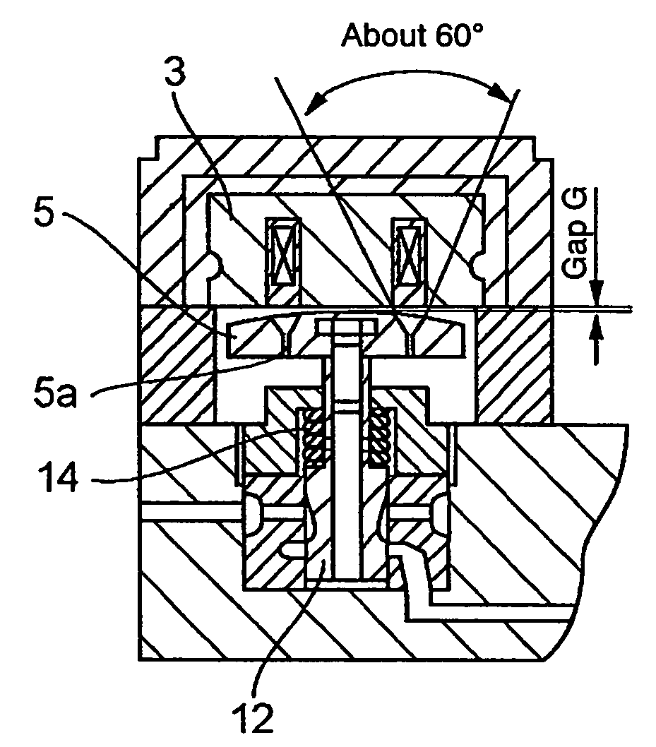
[0045]FIG. 6 shows the In this embodiment, at least one passage hole is provided to the armature 5 in order to attain the object to prevent the occurrence of valve bouncing-when-closing in addition to increasing the electromagnetic attraction through decreasing the margin in initial gap. When the armature 5 is attracted toward the core 3 to lift the valve body 12 to close the high-pressure fuel passage 31, the fuel in the gap between the surfaces of the core 3 and armature 5 is compressed rapidly, and the valve body 12 supported by the spring 14 begins to oscillate due to the impact of the rapid compression. By allowing the fuel in the gap to escape through the passage hole 5a, the impact is relieved and the occurrence of the oscillation is prevented or suppressed. That is, the occurrence of valve bouncing-when-closing is prevented or suppressed. The passage hole 5a is formed to be broadened upwardly in a cone shape so that the fuel in the gap can escape through the passage hole ea...

seventh embodiment

[0047]FIG. 7 shows the In this embodiment, the armature 5 is composed of piled thin plates as in the case of FIG. 5, but composed such that the diameter of a thin plate 5c located remotest from the core3 is about the same as that of the thin plate 5b located nearest to the core 3. At least one passage hole 5a is provided to penetrate the thin plates except for the remotest thin plate 5c, the hole passages 5a being closed by the remotest thin plate 5c near the periphery thereof.

[0048]When the armature 5 is attracted toward the core 3 to lift the valve body 12 to close the high-pressure fuel passage 31, the fuel in the gap between the surfaces of the core 3 and armature 5 is compressed rapidly. The thin plate 5c remotest from the core 3 is bent by the pressure of the compressed fuel as shown in FIG. 9 and the fuel escapes through the gap developed by the bending of the thin plate 5c. Therefore, the occurrence of valve bouncing-when-closing can be prevented or suppressed as in the cas...


PUM

PropertyMeasurementUnit
cone angleaaaaaaaaaa
electromagnetic forceaaaaaaaaaa
distanceaaaaaaaaaa

Abstract

The force to draw an armature of an electromagnetic valve apparatus driving a valve for opening or closing a high-pressure liquid passage is increased and valve bouncing is alleviated by a surface of the core being flat and a surface of the armature facing the surface of the core being shaped convexly spherical. Interference of the surfaces is prevented by a smaller initial gap in a central portion of the faces, even when the armature is installed aslant due to insufficient accuracy of the component parts. Strong electromagnetic attraction can be secured because the smaller the gap is, the stronger the electromagnetic attraction.

Description

BACKGROUND OF THE INVENTION[0001]1. Field of the Invention[0002]The present invention is related to an electromagnetic valve apparatus for driving an open / close valve to open or close a high-pressure fuel passage in order to control fuel injection timing and fuel injection quantity used particularly in the fuel injection equipment of an internal combustion engine.[0003]2. Description of the Related Art[0004]Electromagnetic valve apparatus has been known for driving by utilizing electromagnetic force, an open / close valve to open or close a high-pressure fuel passage in order to control fuel injection timing and fuel injection quantity. The electromagnetic valve apparatus comprises a core with a coil embedded therein and an armature located adjacent to the core. The armature is attracted toward the core when magnetic flux generated by electric current in the coil passes through the armature, and thus a valve body connected to the armature is driven.[0005]As the electromagnetic valve a...

Claims


Application Information

Patent Timeline
Patent Type & Authority Patents(United States)
IPC IPC(8): F02M51/00F02M57/02F02M59/36F02M63/00F16K31/06H01F7/16
CPCF02M63/0015F16K31/061F16K31/0613F16K31/0668H01F7/1638F02M59/366F02M63/0043F02M2200/304H01F2007/086
Inventor KANEKO, TAKASHI
Owner MITSUBISHI HEAVY IND ENGINE & TURBOCHARGER LTD
Why Eureka
Try Eureka