Disposable work light

a work light and light plate technology, applied in the field of portable work lights, can solve the problems of inconvenient use, inconvenient maintenance, and easy breakage of incandescent lamp filaments, and achieve the effects of reducing diameter, limiting light output, and limiting relative movemen

Active Publication Date: 2007-05-22
TFL LIGHTING
View PDF24 Cites 30 Cited by
  • Summary
  • Abstract
  • Description
  • Claims
  • Application Information

AI Technical Summary

Benefits of technology

[0004]Traditionally, trouble lights, such as that disclosed in U.S. Pat. No. 4,275,435 issued to Henry M. Dora on Jun. 23, 1981; U.S. Pat. No. 2,861,175 issued to O. W. Schweikle on Nov. 18, 1958; U.S. Pat. No. 2,677,753 issued G. W. Heinz on May 4, 1954; and U.S. Pat. No. 4,141,062 issued to Raymond L. Trueblood on Feb. 20, 1979, include incandescent lamps which are threadedly received in a complementally formed electrically conductive, threaded, metal light bulb socket that is disposed in, and transversely moveable relative to, a surrounding rubber handle in which the socket is disposed. Incandescent lamps are fragile. If the traditional trouble light is dropped or bumped, the incandescent lamp filament is easily broken. It is an advantage of the present invention to provide a portable work light which will resist lamp breakage due to drops and bumps.
[0005]A substantial amount of heat radiates from incandescent bulbs causing the bulbs to be very hot and subject the user to being burned. The generated heat can also ignite certain inflammable gases and liquids, if inadvertently introduced to the heated incandescent lamp. A hot incandescent lamp can explode if splashed with even one drop of water.
[0006]To overcome these problems, trouble lights have been made with linear fluorescent light sources, such as that disclosed in U.S. Pat. No. 5,975,719 issued to Paul J. Reiff, et al on Nov. 2, 1999; U.S. Pat. No. 6,386,736 issued to Paul J. Reiff, et al on May 14, 2002; U.S. Pat. No. 2,489,686 issued to J. L. Suter on Nov. 29, 1949; U.S. Pat. No. 3,815,080 issued to Frank Summa on Jun. 4, 1974 and U.S. Pat. No. 2,874,270 issued to H. E. Douglas, et al on Feb. 17, 1959. Such elongate, linear light bulbs are bulky, clumsy and limited in their light output. Linear light sources are not concentrated in a short length for a given voltage as are spiral fluorescent bulbs, such as that disclosed in U.S. Pat. No. 2,279,635 issued to J. Morley on Apr. 14, 1942 and U.S. Pat. No. 3,953,761 issued to Thomas Lo Giudice on Apr. 27, 1976. For example, a 15 watt fluorescent bulb is as bright as a 75 watt incandescent bulb which is generally the upper acceptable recommended watt limit for most trouble light fixtures.
[0007]A typical trouble light socket includes a curvilinear metal reflector, fixed to the trouble light handle, extending on one lateral side of the incandescent lamp and a hinged, wire cage along the laterally opposite side of the lamp to protect the lamp from breakage. The prior art housing is mounted on a rubber handle and moveable therewith relative to the bulb subjecting the bulb to breakage. It is an advantage of the present invention to provide a trouble light having a housing which is inseparably fixed to the base of the bulb to limit relative movement therebetween.
[0008]It is another advantage of the present invention to provide a reflector housing of the type described which has a relatively short reflectorized portion and a reduced diameter section mounted on the base of the lamp.
[0009]Yet another advantage of the present invention is to provide a portable work light including a partially reflectorized protective housing cantileverly inseparably mounted to the lamp.

Problems solved by technology

Incandescent lamps are fragile.
If the traditional trouble light is dropped or bumped, the incandescent lamp filament is easily broken.
A substantial amount of heat radiates from incandescent bulbs causing the bulbs to be very hot and subject the user to being burned.
A hot incandescent lamp can explode if splashed with even one drop of water.
Such elongate, linear light bulbs are bulky, clumsy and limited in their light output.

Method used


Image

  • Disposable work light
  • Disposable work light
  • Disposable work light

Examples


Embodiment Construction

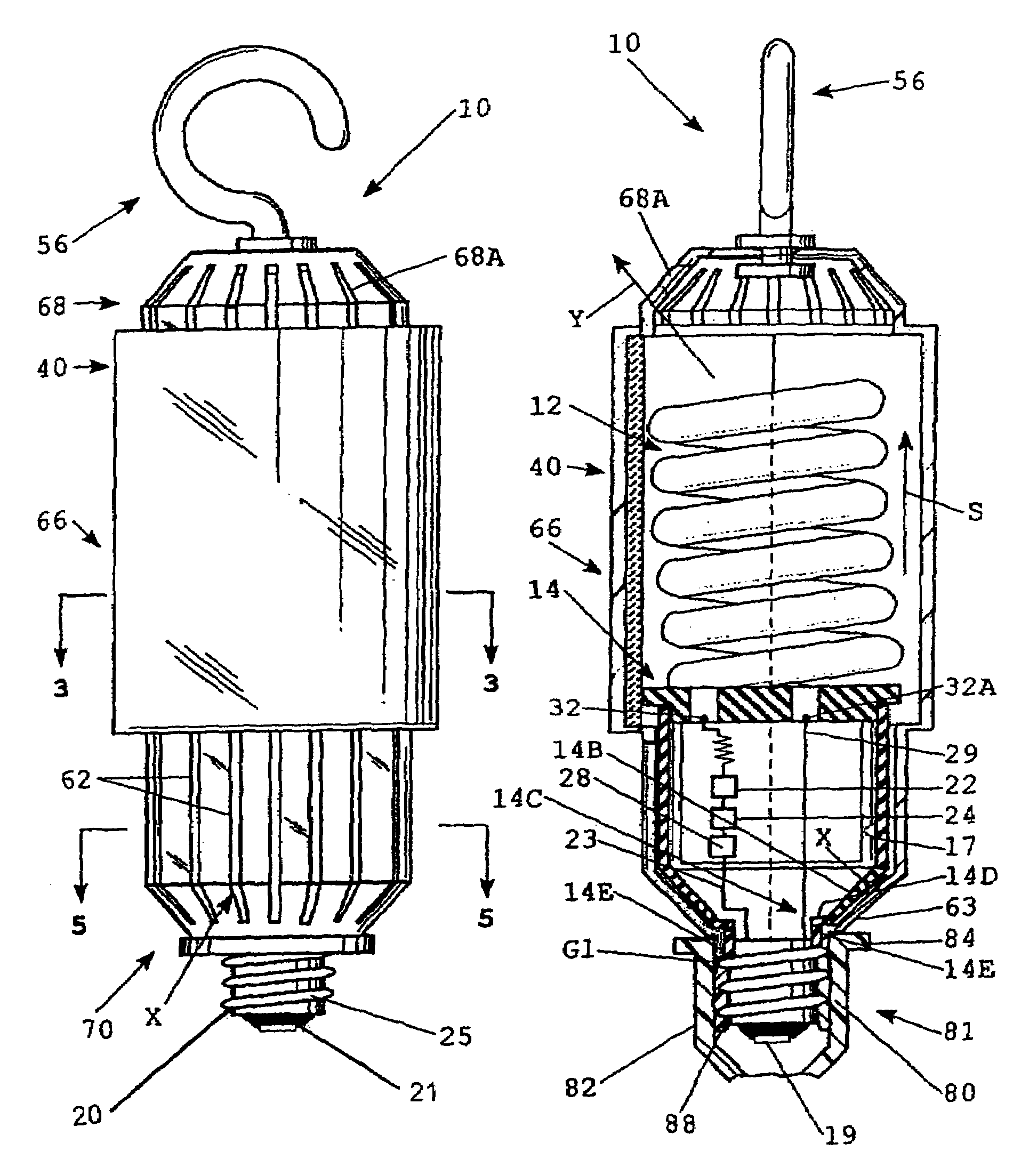
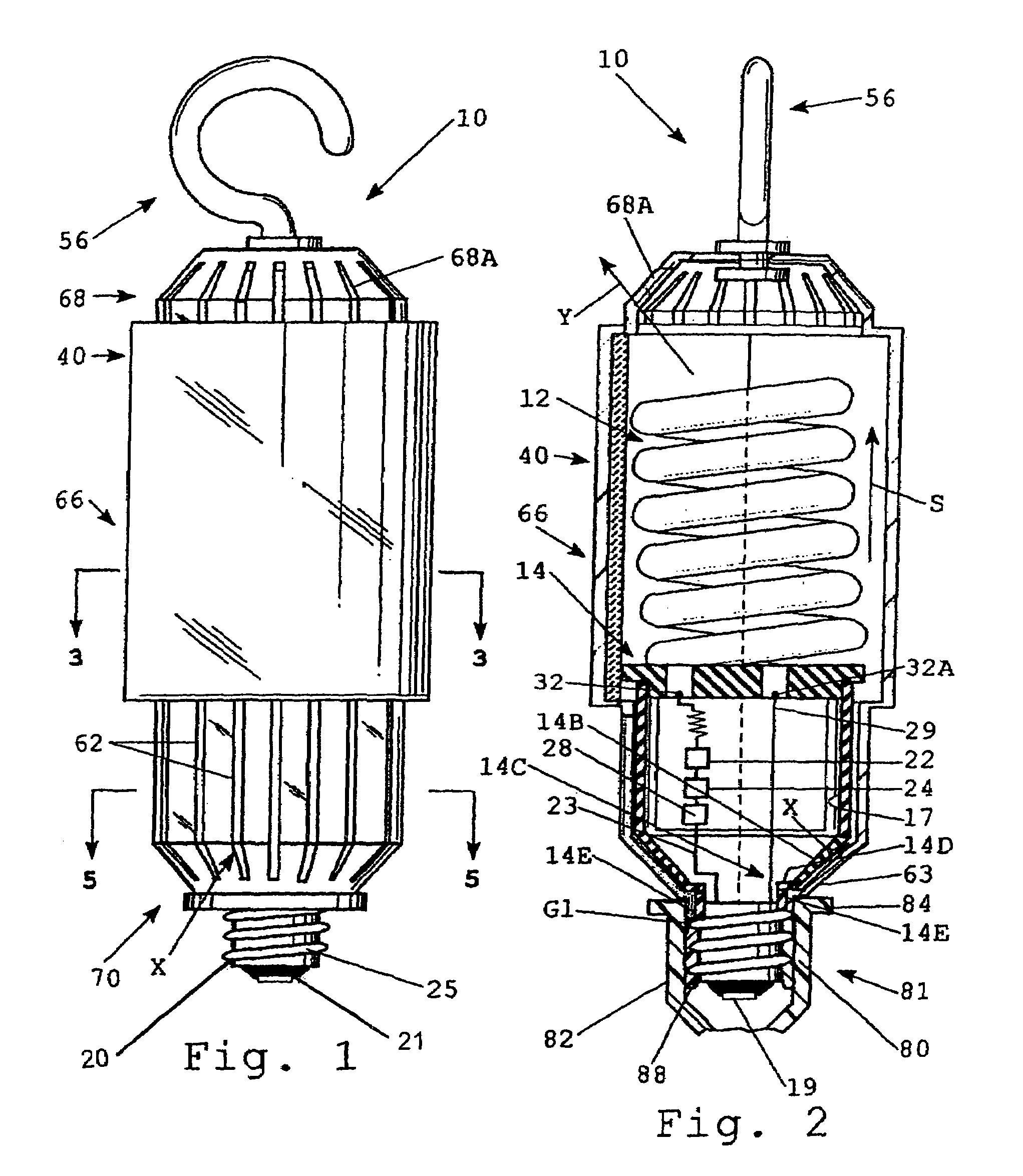
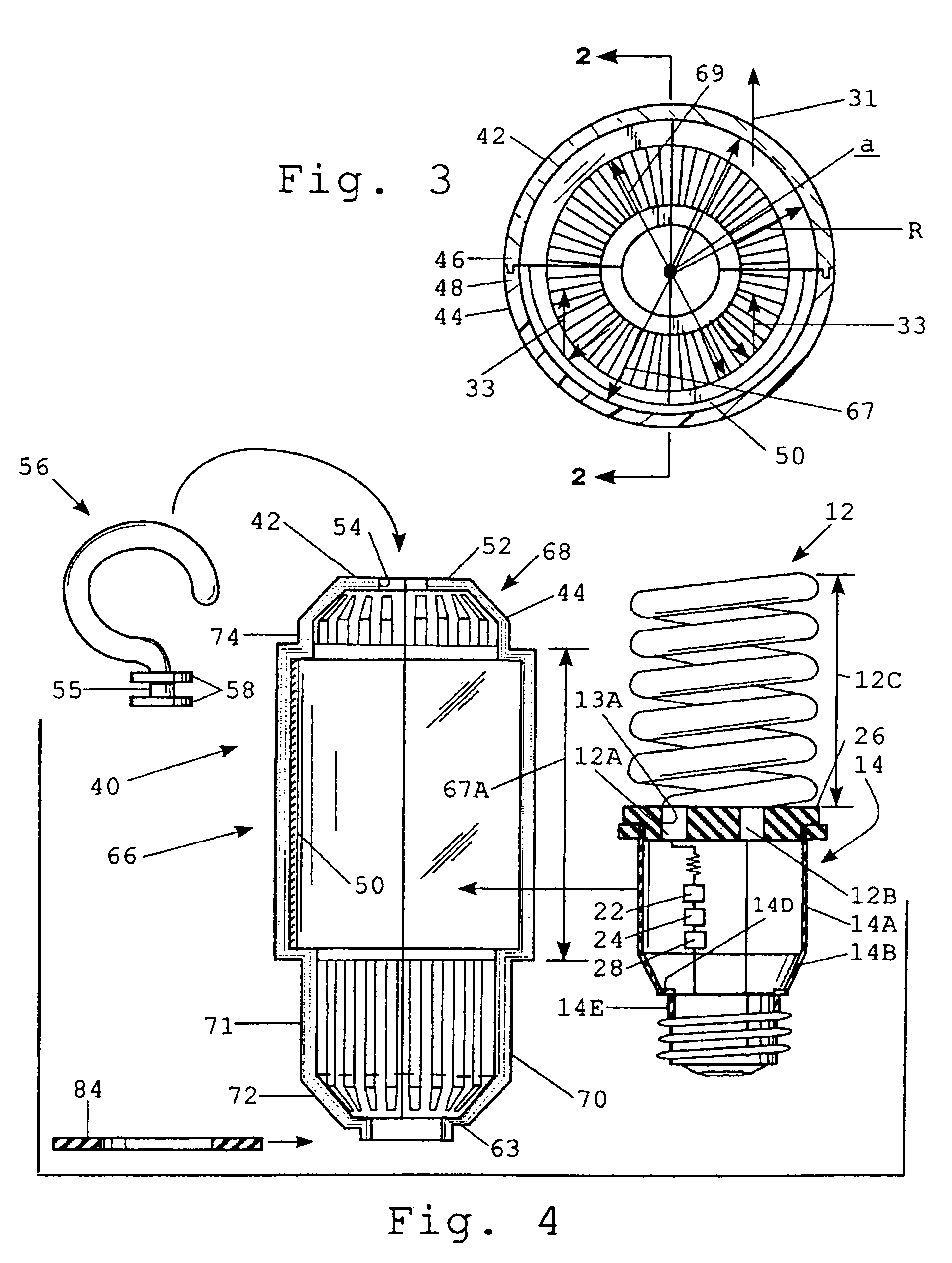
[0025]A disposable work light, generally designated 10, constructed according to the present invention includes a fluorescent lamp or light source, generally designated 12, including an electrically non-conductive, open top hollow one piece base, generally designated 14, which may comprise any electrically non-conductive material, such as plastic. The open top is closed via an electrically non-conductive cap 26 which is press fit into the open top and has a pair of bulb receiving apertures 13A therethrough. The fluorescent light bulb 12 includes a pair of upstanding glass legs 12A and 12B received in the apertures 13A, coupled to a spiral glass configuration 12C having a relatively short axial length 12D. The base 14 has a cavity 17 which receives a ballast or transformer 22, a starter 24 and other assundry electronic circuitry 28 electrically coupled, via line 23, between one terminal 32 of the fluorescent bulb 12 and a central terminal 19 insulated from an electrically conductive ...


PUM


Abstract

A disposable work light including an electrically non-conductive base provided with an electrically conductive terminal adapted to be detachably coupled to a complementally formed electrical socket. An elongate hollow electrically non-conductive cylindrical housing is cantileverly mounted on the base and includes a reflector on one lateral side of a lamp and a translucent housing portion on the laterally opposite of the lamp for passing the reflected, concentrated light to a work site. A transversely disposed, resilient vibration dampener and seal plate is mounted on the base for sealing the work light to the socket and for vibrationally isolating the lamp from the socket.

Description

BACKGROUND OF THE INVENTION[0001]1. Field of the Invention[0002]This invention relates to a portable work light and more particularly, to a disposable work light having a protective and reflectorized housing permanently mounted on the housing lamp.[0003]2. Description of Prior Art and Advantages[0004]Traditionally, trouble lights, such as that disclosed in U.S. Pat. No. 4,275,435 issued to Henry M. Dora on Jun. 23, 1981; U.S. Pat. No. 2,861,175 issued to O. W. Schweikle on Nov. 18, 1958; U.S. Pat. No. 2,677,753 issued G. W. Heinz on May 4, 1954; and U.S. Pat. No. 4,141,062 issued to Raymond L. Trueblood on Feb. 20, 1979, include incandescent lamps which are threadedly received in a complementally formed electrically conductive, threaded, metal light bulb socket that is disposed in, and transversely moveable relative to, a surrounding rubber handle in which the socket is disposed. Incandescent lamps are fragile. If the traditional trouble light is dropped or bumped, the incandescent ...

Claims


Application Information

Patent Timeline
Patent Type & Authority Patents(United States)
IPC IPC(8): F21V7/00
CPCF21L14/02F21V23/00F21V15/01F21V29/83F21V29/004F21V15/00
Inventor BERENDS, BOYD E.
Owner TFL LIGHTING
Why Eureka
Try Eureka