
Accommodating lens assembly

a technology for accommodating lenses and lenses, applied in the field of intraocular lenses, can solve the problems of fixed refractive power, inability to change the focus, and variable degrees of blindness, and achieve the effect of simple and inexpensive construction and large variety of designs

Inactive Publication Date: 2007-05-22
FORSIGHT VISION5 INC
View PDF38 Cites 140 Cited by
  • Summary
  • Abstract
  • Description
  • Claims
  • Application Information

AI Technical Summary

Benefits of technology

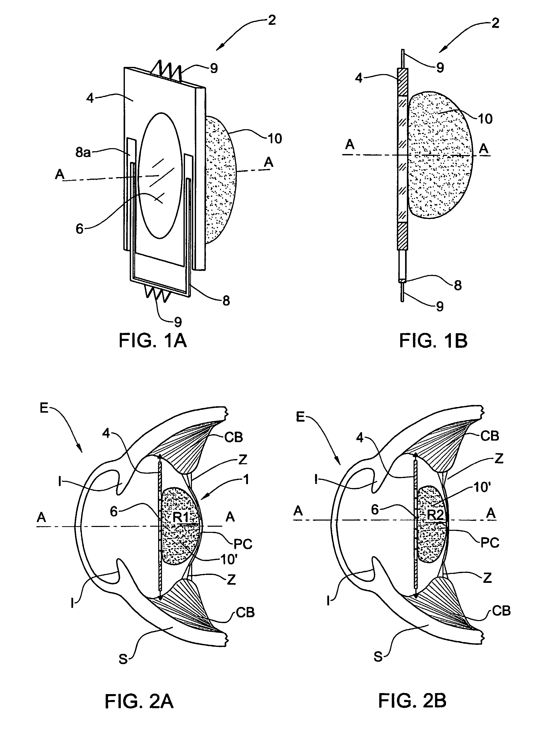
[0010]The lens assembly of the present invention utilizes the natural compression and relaxation of the capsular unit to impart an axial force on the resilient body in order to cause it to act as a lens whose radius of curvature, and therefore the refractive power it provides, varies depending on the magnitude of the force. In this way, the lens assembly cooperates with the natural operation of the eye to accommodate and enable the eye to clearly see objects at different distances.
[0011]The haptics element of the assembly according to the present invention may adopt any of a variety of designs known in the art, e.g. it may be curved or it may be in the form of a plate, which spans a plane essentially perpendicular to the optical axis of the assembly. In addition to the region, the haptics element may be completely transparent. The region of the element may be in the form of a transparent component, such as a clear panel or another lens which may have such a curvature and index of refraction as to enhance the accommodating capability of the lens assembly.
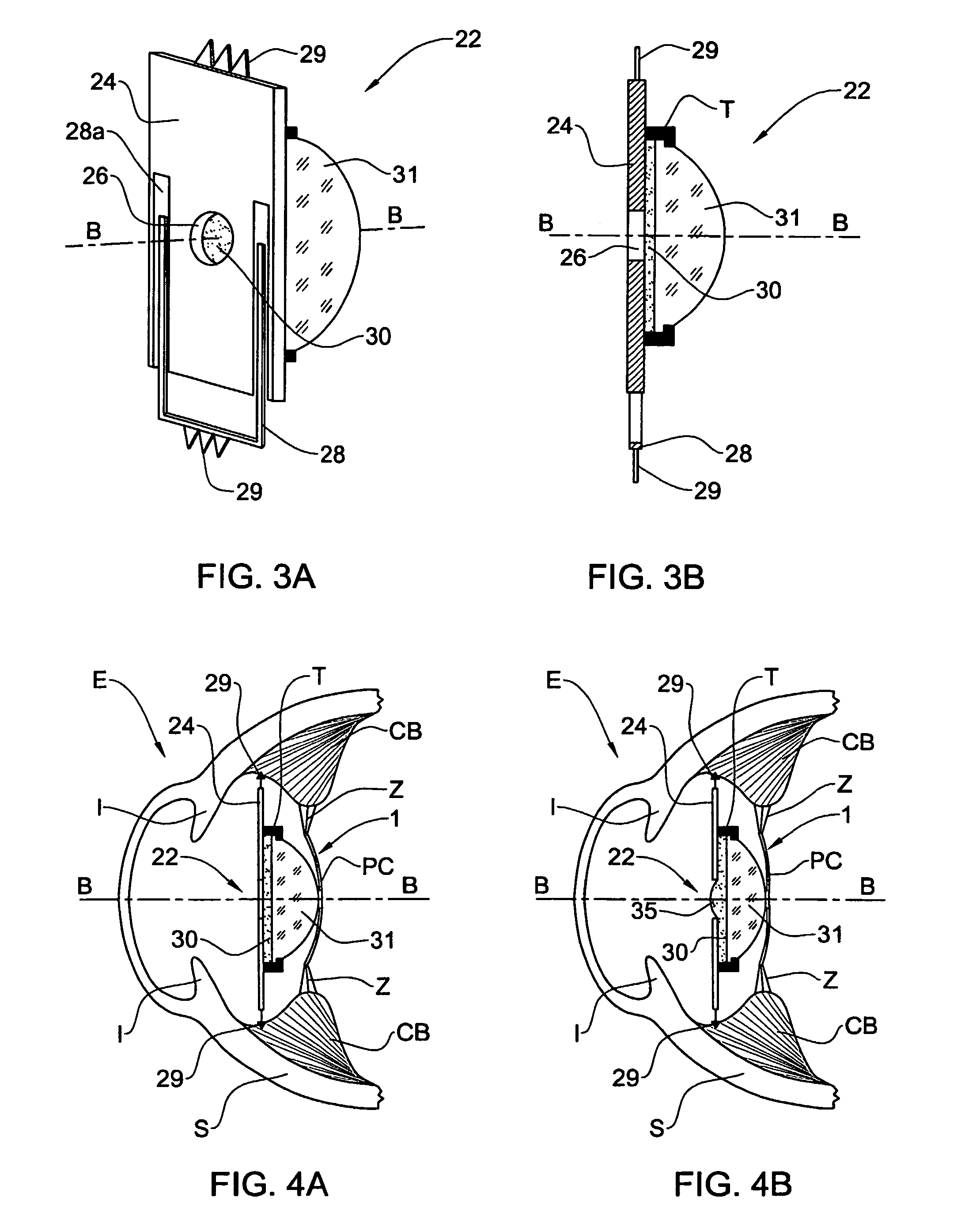
[0012]The haptics element may have a hollow space formed in its transparent region. This hollow space is adapted to allow the resilient body to bulge through the space in response to said force. This enables the lens assembly to provide a range of refractive power (i.e. the accommodating capability) depending on the bulge's radius of curvature, which is determined and may be varied by the magnitude of the force applied by the capsular unit.
[0021]The advantages provided by the accommodating lens assembly of the present invention abound, particularly because of it is designed to be positioned in the eye completely outside of the posterior capsule. One advantage, for example, is that the lens assembly does not undesirably stretch and consequently harm the capsule. Also, the lens assembly does not need to conform to the size or shape of the capsule, and is therefore free to take on a larger variety of designs. Furthermore, the capsule is sometimes damaged during the surgery to remove the natural lens, but the lens assembly of the present invention does not require that the capsule be completely intact in the form of a bag but merely that it remain reliably connected as part of the capsular unit. Another advantage arising from the lens assembly being positioned outside of the posterior capsule is that it remains unaffected by the permanent and unpredictable constriction that the capsule inevitably undergoes due to scarring following the surgery for removal of the natural lens.
[0022]In addition to the above, the lens assembly of the present invention offers advantages such as a simple and inexpensive construction. The lens assembly of the present invention also provides the ability to accommodate within a vast range of refractive power, including the full range provided by the natural eye. Also, the lens assembly provides means for varying its sensitivity in response to the force applied by the capsular unit.

Problems solved by technology

Cataracts occur when the natural lens of the eye or of its surrounding transparent membrane becomes clouded and obstructs the passage of light resulting in various degrees of blindness.
Such lenses, however, have the drawback that they have a fixed refractive power and are therefore unable to change their focus.

Method used


Image

  • Accommodating lens assembly
  • Accommodating lens assembly
  • Accommodating lens assembly

Examples


Embodiment Construction

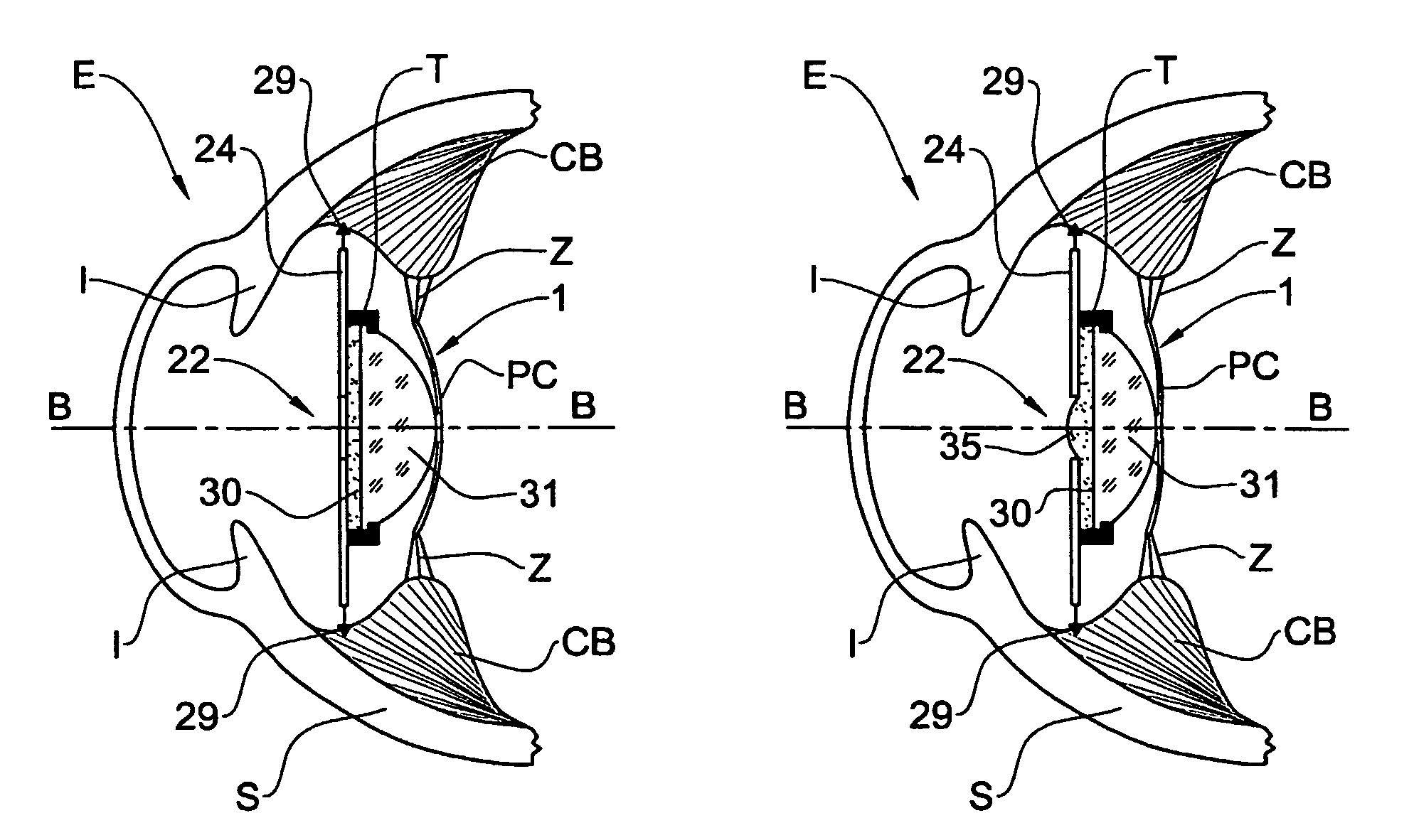
[0034]The subsequent description and figures refer to different examples of an accommodating lens assembly of the present invention and its functional position as implanted in a human eye E. As shown in FIGS. 2A, 2B, 4A, 4B, 5A, and 5B, the eye E, which is filled with natural gel (not shown) having an index of refraction of about 1.3, comprises a scleral wall S, an iris, and a retina R (not shown). The eye E further includes a ciliary body CB, from which extend zonules Z connected to a posterior capsule PC. These last three parts of the eye E constitute the capsular unit 1.

[0035]One example of an accommodating lens assembly in accordance with the present invention adapted for implantation within the eye E is shown in FIG. 1A in plan view and in FIG. 1B from a side view. The accommodating lens assembly 2 has an optical axis A—A and comprises a rigid haptics plate 4 having a first lens 6 made of a rigid material having an index of refraction higher than that of water. The plate 4 furt...


PUM


Abstract

An accommodating lens assembly having an optical axis and being adapted to be implanted in a posterior chamber of an eye having a capsular unit located therein. The assembly includes a rigid haptics element adapted to secure the assembly within the posterior chamber outside said capsular unit. The element is transparent at least in a region around the axis. The assembly further includes a resilient body adapted to operate as a lens having a curved surface when pressed up against the region of the haptics element by an axial force applied thereto by the capsular unit. A change in this force causes a change in a radius of curvature for the curved surface.

Description

FIELD OF THE INVENTION[0001]This invention relates to intraocular lenses, and in particular, to accommodating intraocular lenses capable of focusing on objects located at various distances therefrom.BACKGROUND OF THE INVENTION[0002]The natural lens of a human eye is a transparent crystalline body, which is contained within a capsular bag located behind the iris and in front of the vitreous cavity in a region known as the posterior chamber. The capsular bag is attached on all sides by fibers, called zonules, to a muscular ciliary body. At its rear, the vitreous cavity, which is filled with a gel, further includes the retina, on which light rays passing through the lens are focused. Contraction and relaxation of the ciliary bodies changes the shape of the bag and of the natural lens therein, thereby enabling the eye to focus light rays on the retina originating from objects at various distances.[0003]Cataracts occur when the natural lens of the eye or of its surrounding transparent me...

Claims


Application Information

Patent Timeline
Patent Type & Authority Patents(United States)
IPC IPC(8): A61F2/16A61F
CPCA61F2/1635A61F2/1648A61F2250/0065A61F2220/0016A61F2002/1689
Inventor NUN, YEHOSHUA BEN
Owner FORSIGHT VISION5 INC
Learn More