
Disk array system and failure recovering control method

Inactive Publication Date: 2007-05-22
HITACHI LTD
View PDF16 Cites 23 Cited by
  • Summary
  • Abstract
  • Description
  • Claims
  • Application Information

AI Technical Summary

Benefits of technology

[0021]The object of the invention is to provide a disk array system and a failure recovering control method suitable for miniaturizing body size of the disk array and increasing memory capacity.
[0023]Further another object of the invention is to provide a disk array system and a failure recovering control method allowable sufficient work time in replacing a faulty drive by maintenance personnel when failure occurs in the drive.
[0025]Data stored in the faulty drive is required to be regenerated based upon data read out from the other drives that belong to the same logical group as the faulty drive. However, as for data stored in the normal drives on the faulty board, data in the normal drives on the faulty board has only to be copied into the substitution disk drives as it is, the transfer of the data from the normal drives to the substitution disk drives can be completed in short time. According to the invention, as the faulty board is replaced after the reorganization of the logical groups is completed, normal data reading / writing is enabled even while the faulty board is detached from the disk array, and there is no need to regenerate data in the absent drive based on the logical groups as in the prior art when read / write command is executed.

Problems solved by technology

As a result, the packaging density of drive boards on the mother board is deteriorated.
It can be said that the disk array system proposed in the patent document 1 has hardware configuration suitable for miniaturizing body size and increasing memory capacity, however, when a data read request is issued from the host system while the faulty board is detached, operation for regenerating data based on the logical group is required for not only the faulty drive but for a plurality of normal drives made absent, and such a problem that a response to a data read request is delayed is caused while the faulty board is detached from the disk array.

Method used


Image

  • Disk array system and failure recovering control method
  • Disk array system and failure recovering control method
  • Disk array system and failure recovering control method

Examples


Embodiment Construction

[0052]Referring to the drawings, embodiments of the invention will be described below.

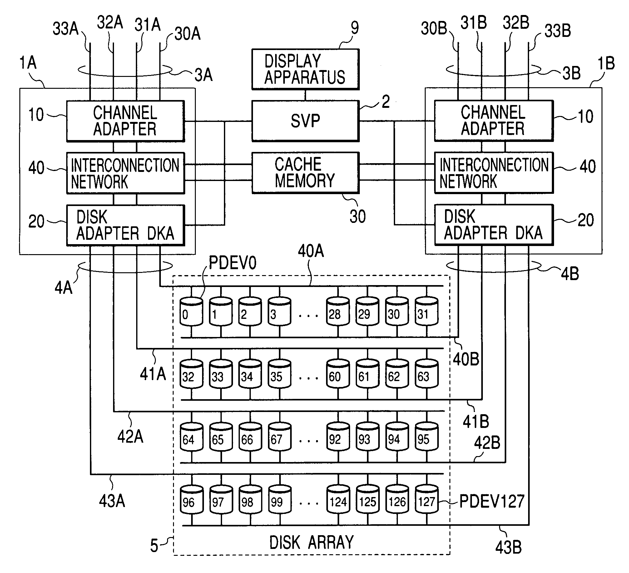
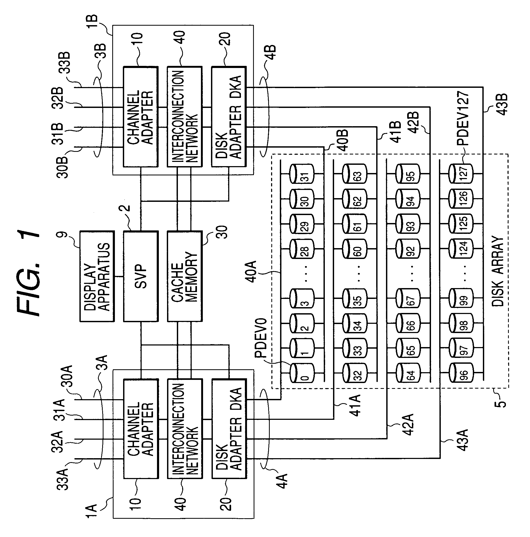
[0053]FIG. 1 shows an embodiment of a disk array system to which the invention is applied.

[0054]The disk array system shown in FIG. 1 has redundant configuration that two disk controllers 1A, 1B access a disk array 5 composed of a plurality of disk drives. These disk controllers 1A, 1B are connected to a service processor (SVP) 2 provided with a display apparatus 9. The disk controller 1A is composed of a channel adapter 10 connected to CPU (not shown) as a host system via a plurality of channel paths 3A (30A to 33A), a disk adapter (DKA) 20 connected to the disk array 5 via a plurality of disk channels 4A (40A to 43A) including a signal line for bypass control described later and an interconnection network 40 mutually connecting these components.

[0055]In this embodiment, description will be made on the premise that the number of disk drives forming each logical group (hereinafter called a RAID gro...


PUM


Abstract

In a disk array system composed of a disk controller connected to a host system and a maintenance terminal and a disk array connected to the disk controller via a disk channel, when failure occurs in a drive in the disk array, the disk controller writes data stored in a plurality of disk drives on a faulty board on which a faulty drive is mounted into substitution disk drives and informs the maintenance terminal that the faulty board is replaceable after the reorganization of logical groups is completed.

Description

BACKGROUND OF THE INVENTION[0001](1) Field of the Invention[0002]The present invention relates to a disk array system and a failure recovering control method, further detailedly relates to a disk array system of a redundant array of inexpensive disks (RAID) type which forms one logical group by a plurality of disk drives including a redundant disk drive to prepare for the failure of any disk drive and a failure recovering control method.[0003](2) Description of the Related Art[0004]A high-performance computer system is provided with a secondary mass storage and reads and writes data required by a host system such as CPU from and to the secondary storage at any time. For the secondary storage, for example, a disk unit having a nonvolatile storage medium that enables random access such as a magnetic disk and an optical disk is general and recently, a disk array system composed of multiple small-sized disk drives (hereinafter called merely drives) to increase storage capacity is mainst...

Claims


Application Information

Patent Timeline
IPC IPC(8): G06F11/00H02H3/05G06F3/06
CPCG06F11/1092
Inventor TANAKA, KATSUYAUEMURA, TETSUYA
Owner HITACHI LTD
Learn More