Magnetic sensor

Inactive Publication Date: 2005-01-20
NAT INST OF ADVANCED IND SCI & TECH +1
View PDF3 Cites 4 Cited by
  • Summary
  • Abstract
  • Description
  • Claims
  • Application Information

AI Technical Summary

Benefits of technology

[0015] Accordingly, a first object of the present invention is to make it possible to reproduce a magnetic record even if the size of a recorded magnetization is a minute one, such as a size of several hundred or several ten Angstroms, or a lattice size of several Angstroms. This will drastically increase the memory capacity of a magneto-optical disk or HDD. This method is principally different from that of the conventional Kerr rotation mechanism or magnetoresistive mechanism. This method provides a magnetic sensor that utilizes the rotation of the polarization plane of a second harmonic of the reflected light with respect to incident light, based on the nonlinear optical response theory associated with the asymmetry of a magnetic material.
[0016] A second object of the present invention is to provide a magnetic sensor that does not impose limitations on the incident light intensity, that is, a magnetic sensor that allows a magnetization recorded on a magneto-optical disk to be directly read without applying incident light itself to the magneto-optical disk. This is for circumventing the risk of unnecessarily raising the temperature of the recording medium during reproduction to such an extent that the recording medium is heated up to a higher temperature than the transition temperature of magnetization.
[0017] According to the magnetic sensor of the present invention, it is possible to detect a magnetic field from the magneto-optical disk by applying semiconductor laser light to the magnetic sensor element and detecting a second harmonic, which is an output from the element. In this

Problems solved by technology

Due to bloated information industries and storages of image information a

Method used


Image

  • Magnetic sensor
  • Magnetic sensor
  • Magnetic sensor

Examples


first embodiment

[0068] An concrete example having a superlattice structure and used as a magnetic sensor element is shown below.

[0069]FIG. 3 is a sectional view showing the structure of an LSMO magnetic sensor element with a superlattice structure according to the present invention.

[0070] This superlattice employed the (100) plane of SrTiO3 (abbreviated as STO) 201 as a substrate. On this substrate (100) plane, ten molecular layers of La0.6Sr0.4MnO3 (abbreviated as LSMO) 202 were stacked. On these LSMO layers, two molecular layers of LaAlO3 (abbreviated as LAO) 203 and three molecular layers of STO 204 were stacked. The film thickness in a single layer is 3.824 Å for LSMO 202, 3.750 Å for LAO 203, and 3.905 Å for STO 204. With the structure constituted of these molecular layers of LSMO 202, LAO 203, and STO 204 were treated as one unit, ten units thereof were stacked on the above-described structure. The film thickness of the one unit is 57.45 Å, that of the ten units being 574.55 Å. The stacking...

second embodiment

[0087] A concrete example is shown in which a rhombic crystal GaFeO3 is incorporated in a magnetic sensor.

[0088] This crystal has a rhombic crystal structure, and it has a space group of Pc21n according to the classification table of space groups. This crystal has a structure such that the easy magnetization axis thereof constitutes a c-axis, and the polarization axis thereof constitutes a b-axis. The dispositions of this crystal structure, the polarization direction of incident light, and an SHG signal are shown in FIG. 8.

[0089]FIG. 8 is a diagram showing the disposition relationship between the crystal structure of the GaFeO3 magnetic sensor element according to the present invention and laser light. Here, the polarization axis, i.e., b-axis, of GaFeO3 is arranged to be a z-axis, and the easy magnetization axis thereof is arranged to be an x-axis. Laser light is made incident parallel to the b-axis, i.e., along the z-axis direction.

[0090] In FIG. 8, reference numeral 601 denote...


PUM


Abstract

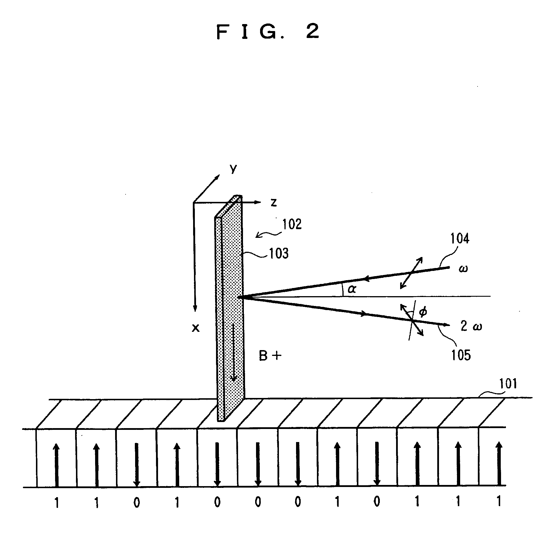
The present invention provides a magnetic sensor capable of reproducing a magnetic record even if the size of a recorded magnetization is a minute one, directly reading a magnetization recorded on a magneto-optical disk without applying incident light itself to the magneto-optical disk, and obtaining signals of a second harmonic having a high S/N ratio. This magnetic sensor includes a magnetic sensor element (102) having electric polarization disposed with respect to a perpendicular recording medium (101), and laser generating means acting on the magnetic sensor element (102). The magnetic sensor reads information in the perpendicular recording medium (101) based on the variation of the rotation angle φ of the polarization plane of a second harmonic (105) of a frequency 2ω exiting the magnetic sensor element (102) by the application of laser light (104) with a frequency ω from the laser generation means to the magnetic sensor element (102).

Description

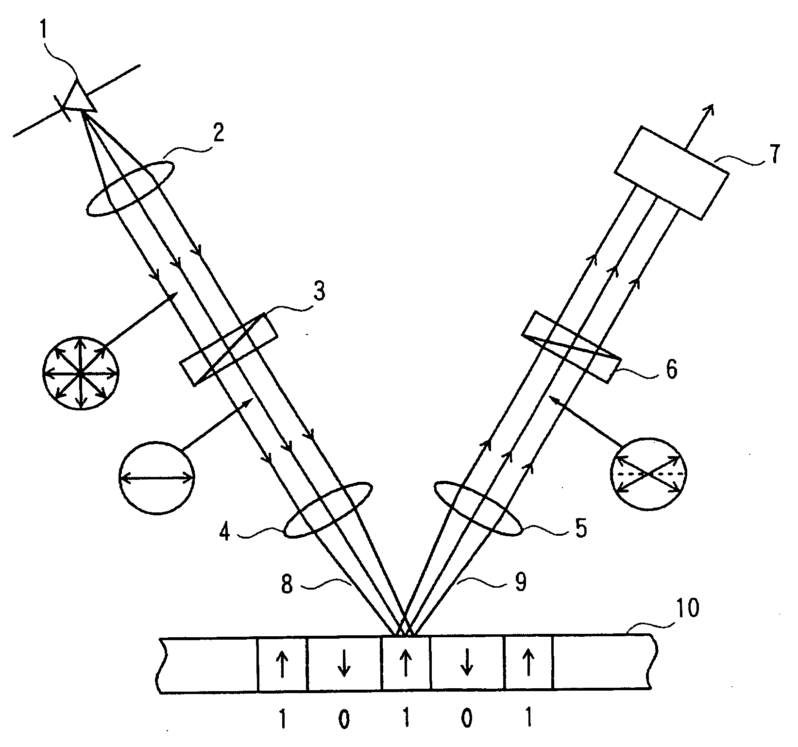
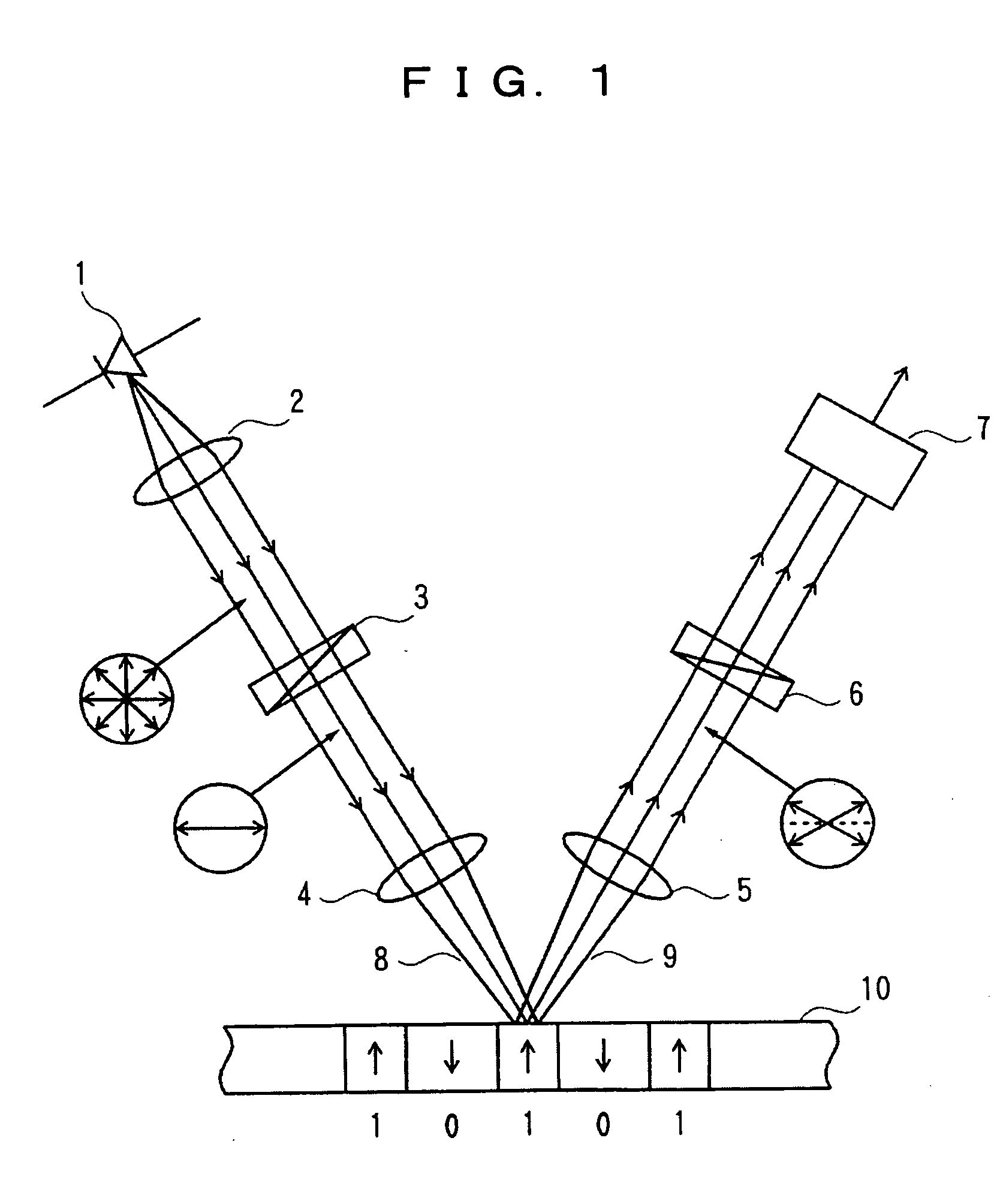
DESCRIPTION [0001] 1. Technical Field [0002] The present invention relates to a magnetic sensor. More specifically, the present invention pertains to a magnetic sensor element using a second harmonic, and allowing spin information imbedded within a solid, such as a magneto-optical disk or hard disk device (HDD), to be read out (reproduced) with high sensitivity and high spatial resolution. [0003] 2. Background Art [0004] For the reproduction of information recorded on a magneto-optical disk, the Kerr effect of reflected light, which is a magneto-optical effect, is conventionally utilized. [0005]FIG. 1 is a diagram explaining the reproduction principle of such a conventional magneto-optical disk. [0006] In FIG. 1, reference numeral 1 denotes a semiconductor laser, numerals 2, 4, and 5 denote lenses, numeral 3 denotes a polarizer, numeral 6 denotes an analyzer, numeral 7 denotes a photodiode, numeral 8 denotes incident light, numeral 9 denotes reflected light, and numeral 10 denotes a...

Claims


Application Information

Patent Timeline
IPC IPC(8): G01R33/032G11B5/127G11B11/105
CPCG01R33/0325G01R33/095G11C13/06G11B11/10547G11B5/1278G01R33/02
Inventor TOKURA, YOSHINORIKAWASAKI, MASASHIYAMADA, HIROYUKIOGAWA, YOSHIHIROKANEKO, YOSHIO
Owner NAT INST OF ADVANCED IND SCI & TECH
Why Eureka
Try Eureka