Measurement device and measurement method
- Summary
- Abstract
- Description
- Claims
- Application Information
AI Technical Summary
Benefits of technology
Problems solved by technology
Method used
Image
Examples
first embodiment
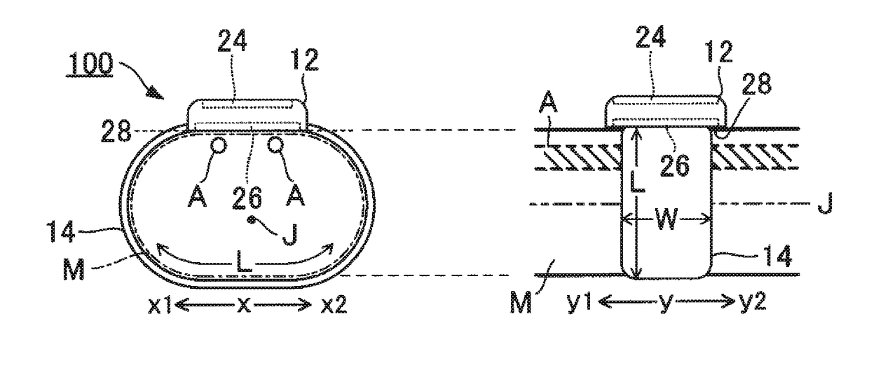
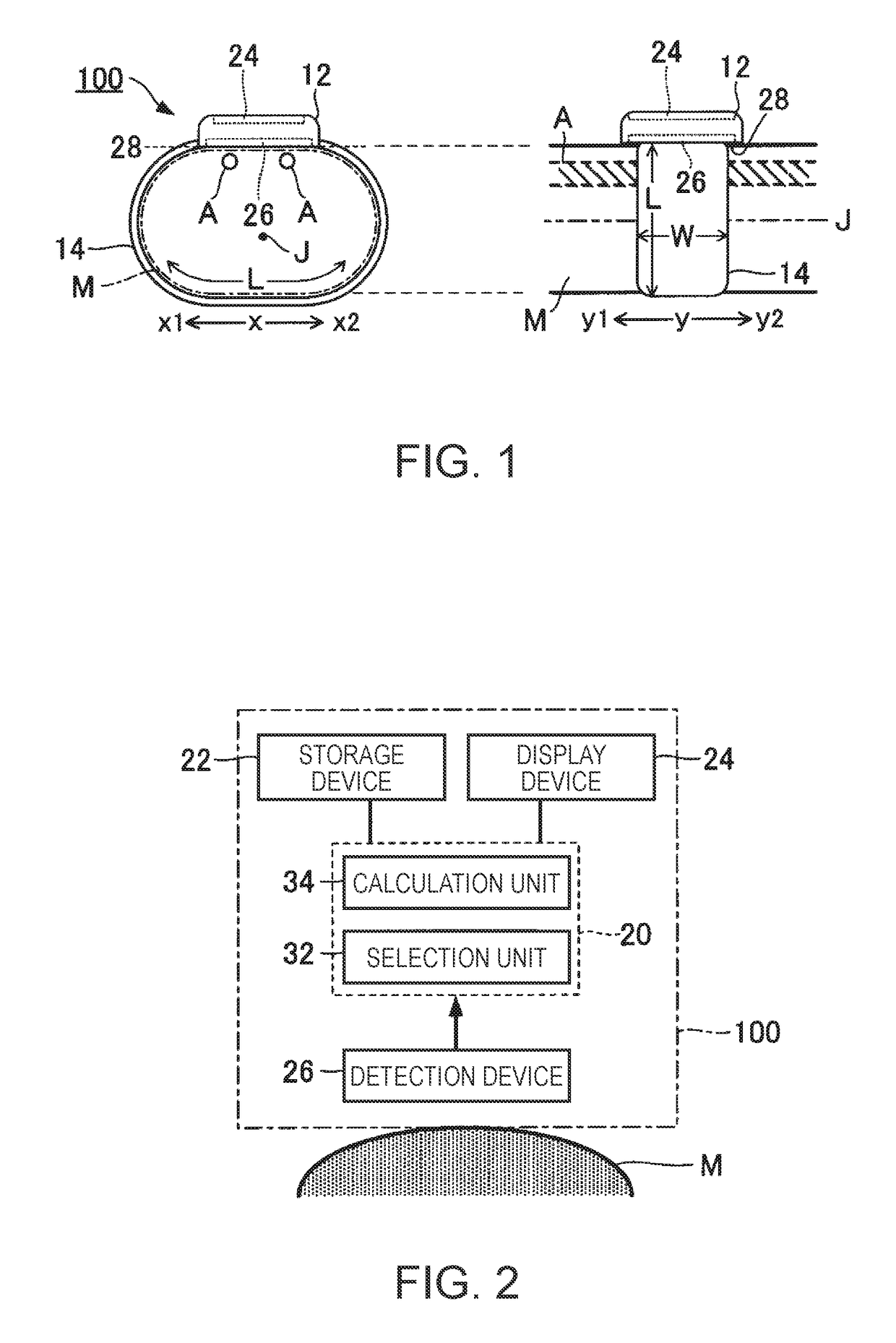
[0028]FIG. 1 is a side view of a measurement device 100 according to a first embodiment of the invention. The measurement device 100 is a measuring instrument for calculating biological information relating to a blood flow of a subject, and is mounted on a site to be measured (hereinafter, referred to as a “measurement target site”) M of a body of the subject. In the first embodiment, a wrist of the subject will be described as an example of the measurement target site M. Specifically, the measurement device 100 calculates the biological information relating to the blood flow of an artery A (radial artery and ulnar artery) present inside the measurement target site M. In the first embodiment, a blood flow rate of the artery A will be described as an example of the biological information relating to the blood flow.
[0029]The measurement device 100 according to the first embodiment is a wristwatch-type portable instrument including a belt 14 wrapped around the measurement target site M...
second embodiment
[0047]A second embodiment according to the invention will be described. In each configuration described below as an example, the reference numerals used in describing the first embodiment will be used for elements whose operation or function is the same as that according to the first embodiment, and each detailed description thereof will be appropriately omitted.
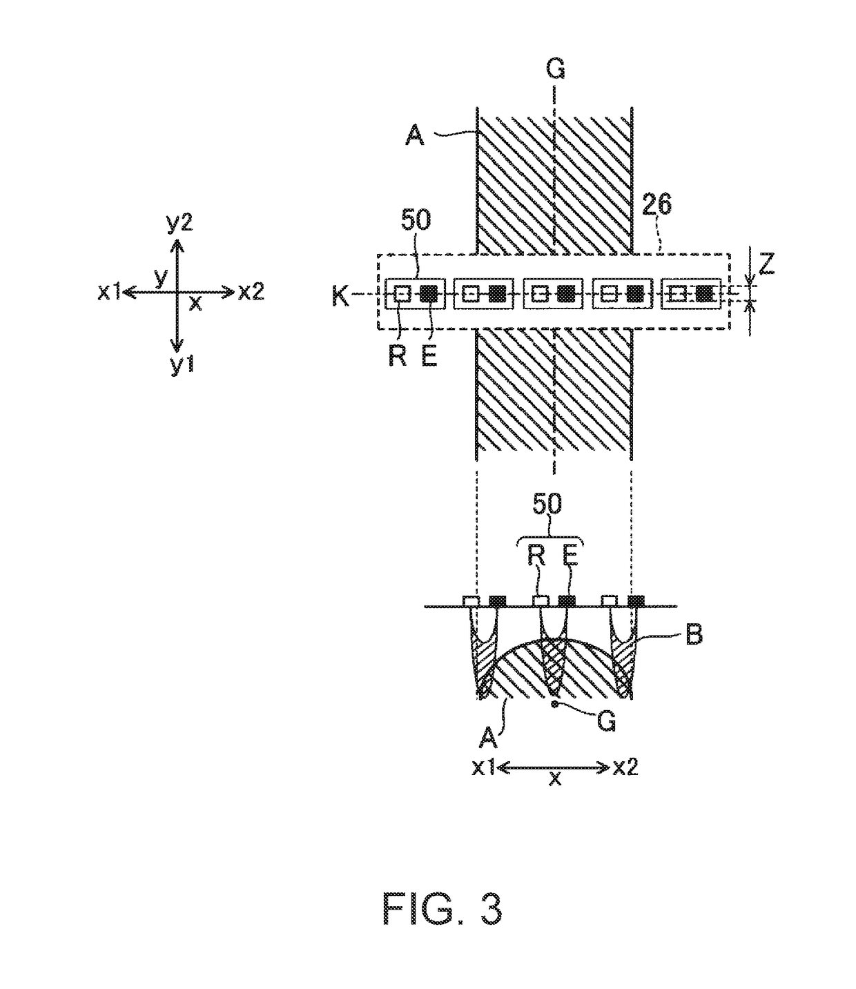
[0048]In the first embodiment, the light emitting unit E and the light receiving unit R in each of the plurality of detection units 50 are located along the first direction x. In contrast, in the second embodiment, as illustrated in FIG. 7, the light emitting unit E and the light receiving unit R in each of the plurality of detection units 50 are located along the second direction y intersecting the first direction x.
[0049]Similarly to the first embodiment, the detection device 26 according to the second embodiment includes a plurality of detection units 50. Similarly to the first embodiment, the plurality of detection units...
modification example
[0053]Each embodiment described above can be modified in various ways. Hereinafter, specific modification aspects will be described. Two or more optionally selected aspects from the following examples can be appropriately combined with each other.
[0054](1) In each of the above-described embodiments, the S / N ratio has described as an example of the intensity index. However, the intensity index is not limited to the above-described example. For example, a configuration can be adopted in which the signal intensity itself of the detection signal is set as an example of the intensity index. A representative value (average value or maximum value) of the intensity within a specific range (for example, one cycle or a plurality of cycles) can be used as the intensity index.
[0055](2) In each of the above-described embodiments, the blood flow rate Q is calculated as the biological information relating to the blood flow inside the measurement target site M. However, a type of the biological inf...
PUM
 Abstract
Description
Claims
Application Information
 - R&D
- Intellectual Property
- Life Sciences
- Materials
- Tech Scout
- Unparalleled Data Quality
- Higher Quality Content
- 60% Fewer Hallucinations
Browse by: Latest US Patents, China's latest patents, Technical Efficacy Thesaurus, Application Domain, Technology Topic, Popular Technical Reports.
© 2025 PatSnap. All rights reserved.Legal|Privacy policy|Modern Slavery Act Transparency Statement|Sitemap|About US| Contact US: help@patsnap.com


