Modulated signal detecting apparatus and modulated signal detecting method

Active Publication Date: 2013-10-17
PANASONIC INTELLECTUAL PROPERTY MANAGEMENT CO LTD
View PDF1 Cites 3 Cited by
  • Summary
  • Abstract
  • Description
  • Claims
  • Application Information

AI Technical Summary

Benefits of technology

The present invention cancels out a phase difference error component that is caused by changes in the optical path between two light beams. This allows for the detection of a high-quality modulated signal with a high signal-to-noise ratio.

Problems solved by technology

However, since light in an ultraviolet range equal to or shorter than 300 nm attenuates significantly in air, wavelength reduction of laser light cannot be expected to produce major benefits.
However, since optical interference is used, a fluctuation in a difference between an optical path length of signal light and an optical path length of reference light causes a variation in an optical phase relationship between the signal light and the reference light and creates a noise component in a reproduction signal.
A decline in the S / N of signal light limits progress toward realizing an apparatus with a high transmission rate and high density in the optical disk field.
If a constant relationship between an average phase of the signal light to be detected and a phase of the reference light to be interfered cannot be maintained, a detection sensitivity of a detected signal declines significantly.
When a fluctuating factor exists on an optical path length, there is a problem that controlling the optical path length becomes extremely difficult.
Tracking fluctuations in the optical path length at an accuracy of several ten nm by an actuator is extremely difficult and, in particular, fluctuations become totally uncontrollable at frequency bands that are higher than a certain level.
Therefore, in order to put the technique described in Patent Literature 2 into practice, fluctuation due to undulation of a recording surface of an optical disk medium must be reduced to almost zero and the fluctuation had been a major obstacle toward practical realization.
The issue of undulation of the recording surface of an optical disk medium causing a fluctuation in the optical path length of reference light and the optical path length of signal light also applies to the configuration according to Patent Literature 3, making practical realization extremely difficult.
Since the frequency of light is extremely high, an optical phase cannot be directly detected using modern technology.
Therefore, an optical phase cannot be detected by any other method than detecting an optical phase using optical interference between signal light and reference light.
However, since the wavelength of light used in optical communication, an optical bus, or an optical disk medium ranges from several μm to 400 nm and is extremely short, the technique described above (a phase detection technique by reference light using optical interference) requires a technique that accurately controls average phases of reference light and signal light at several tenths of the wavelength of light.
Therefore, when a range of optical path length fluctuation is significantly large compared to a range of phase modulation at extremely short wavelengths ranging from several μm to 400 nm, a phase noise component due to the optical path length fluctuation causes an arc tangent output phase to cross over to a discontinuous portion and prevents a correct output from being obtained.

Method used


Image

  • Modulated signal detecting apparatus and modulated signal detecting method
  • Modulated signal detecting apparatus and modulated signal detecting method
  • Modulated signal detecting apparatus and modulated signal detecting method

Examples


first embodiment

[0063]FIGS. 1, 2, and 4 are schematic diagrams showing a configuration of a modulated signal detecting apparatus according to a first embodiment of the present invention. Hereinafter, the present first embodiment will be described in detail.

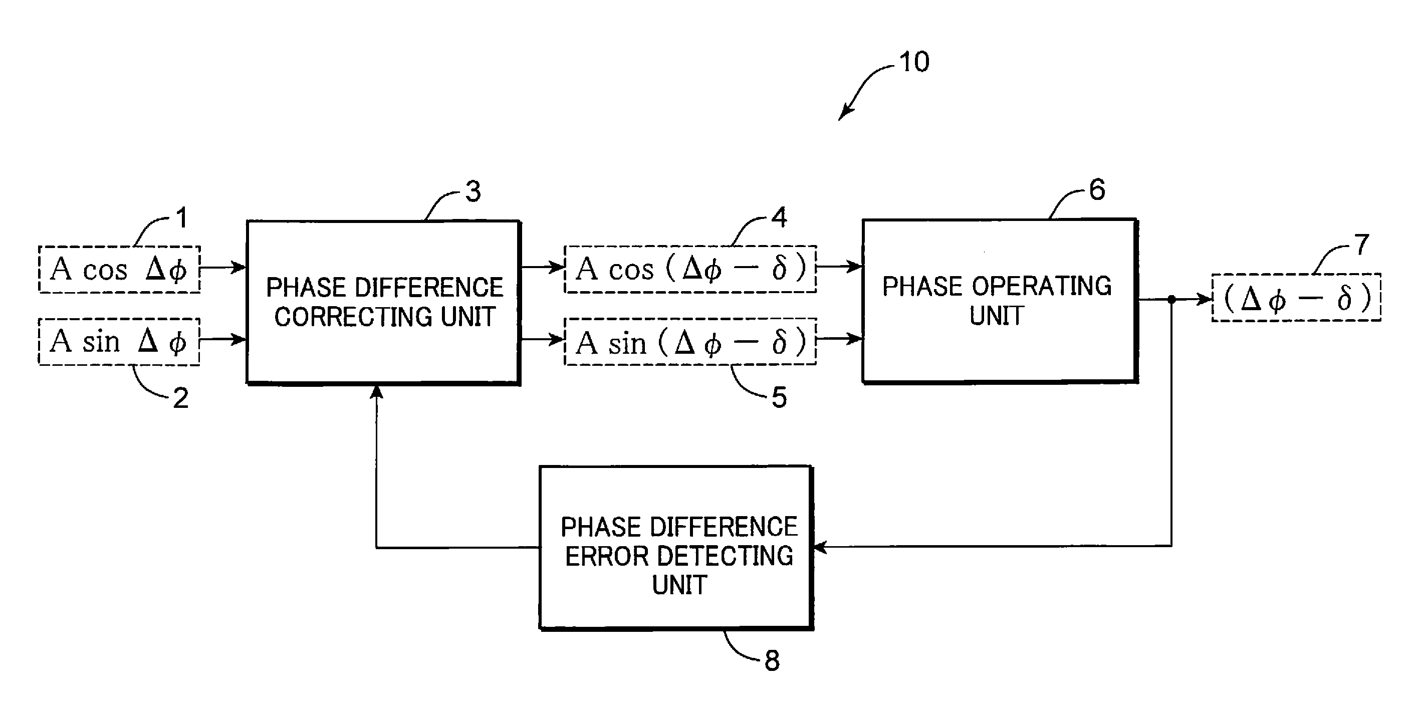
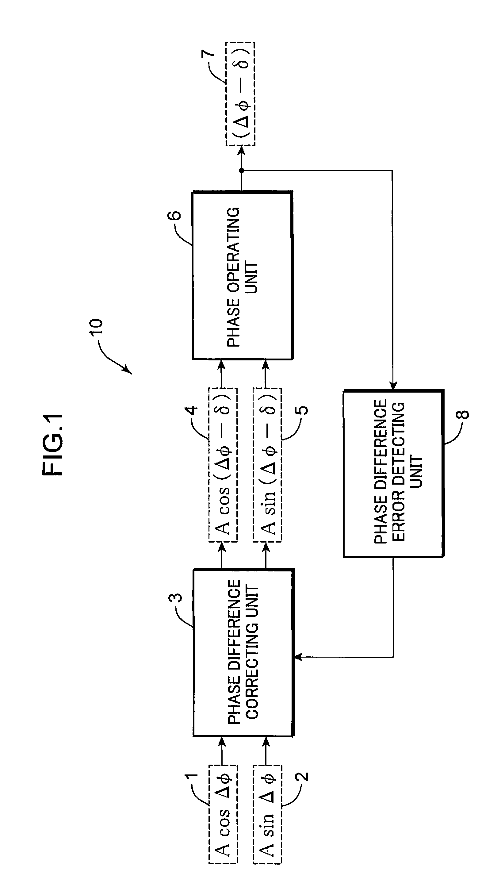
[0064]FIG. 1 is a diagram showing a configuration of a phase difference operating unit according to the first embodiment of the present invention. In FIG. 1, a phase difference operating unit 10 comprises a phase difference correcting unit 3, a phase operating unit 6, and a phase difference error detecting unit 8. A cosine component 1 and a sine component 2 are inputted to the phase difference correcting unit 3. The cosine component 1 has a phase difference (an optical path difference) Δφ between reference light and signal light. The sine component 2 has an amplitude that is approximately equal to that of the cosine component 1 and a phase difference of approximately π / 2 from the cosine component 1.

[0065]In this case, a deviation in phase differe...

second embodiment

[0106]FIGS. 9 and 10 are schematic diagrams showing a configuration of a modulated signal detecting apparatus according to a second embodiment of the present invention. Hereinafter, the present second embodiment will be described in detail.

[0107]In FIGS. 9 and 10, same components as those shown in FIGS. 1 and 2 are denoted by same reference numerals and descriptions thereof will be omitted.

[0108]FIG. 9 is a diagram showing a configuration of a phase difference operating unit according to the second embodiment of the present invention. In FIG. 9, a phase difference operating unit 20 comprises a phase difference correcting unit 51 and a phase operating unit 6. A cosine component 1 and a sine component 2 are inputted to the phase difference correcting unit 51. The cosine component 1 has a phase difference (an optical path difference) Δφ between reference light and signal light. The sine component 2 has an amplitude that is approximately equal to that of the cosine component 1 and a pha...

third embodiment

[0126]FIGS. 11 and 12 are schematic diagrams showing a configuration of a modulated signal detecting apparatus according to a third embodiment of the present invention. Hereinafter, the present third embodiment will be described in detail.

[0127]In FIGS. 11 and 12, same components as those shown in FIGS. 1 and 2 are denoted by same reference numerals and descriptions thereof will be omitted.

[0128]FIG. 11 is a diagram showing a configuration of a phase difference operating unit according to the third embodiment of the present invention. In FIG. 11, a phase difference operating unit 30 comprises a phase difference correcting unit 71 and a phase operating unit 6. A cosine component 1 and a sine component 2 are inputted to the phase difference correcting unit 71. The cosine component 1 has a phase difference (an optical path difference) Δφ between reference light and signal light. The sine component 2 has an amplitude that is approximately equal to that of the cosine component 1 and a ph...


PUM


Abstract

A phase difference error detecting unit detects a phase difference error component included in a phase difference component; a phase difference correcting unit corrects a first signal having the phase difference component as an angle of a cosine function and a second signal whose angle of the cosine function differs from that of the first signal by approximately π / 2 based on the detected phase difference error component; a phase operating unit operates a phase difference component from the first signal and the second signal corrected by the phase difference correcting unit; and the phase difference correcting unit obtains the corrected first signal and the corrected second signal by rotating a coordinate point represented by the first signal and the second signal on a polar coordinate plane by an angle corresponding to the phase difference error component.

Description

TECHNICAL FIELD[0001]The present invention relates to a modulated signal detecting apparatus and a modulated signal detecting method for detecting a modulated signal by detecting interference light resulting from an interference between intensity-modulated or phase-modulated signal light and reference light, and provides a technique that is applicable to an optical disk medium, optical data transmission, optical data communication, an optical bus, an optical USB (universal serial bus), and the like.BACKGROUND ART[0002]Optical disk media are widely used as large capacity information recording media. Technological development for increasing capacities of optical disk media has proceeded from CDs to DVDs and then to Blu-ray Discs by using laser light of shorter wavelengths and objective lenses with higher numerical apertures (NA). Recently, given that services known as cloud services that utilize online storage on the Internet have been expanding year after year, further capacity enlar...

Claims


Application Information

Patent Timeline
IPC IPC(8): G02F2/00
CPCG02F2/00G11B7/1365G11B7/1395G11B20/10268H04B10/6165H04L27/223H04L27/2271
Inventor ITO, KIYOTAKAHINO, YASUMORI
Owner PANASONIC INTELLECTUAL PROPERTY MANAGEMENT CO LTD
Why Eureka
Try Eureka