Optical head apparatus and optical information recording or reproducing apparatus
Inactive Publication Date: 2005-04-28
NEC CORP
View PDF11 Cites 9 Cited by
Summary
Abstract
Description
Claims
Application Information
AI Technical Summary
This helps you quickly interpret patents by identifying the three key elements:
Problems solved by technology
Method used
Benefits of technology
Benefits of technology
[0017] An object of the present invention is to solve the above-described problems in the conventional optical head apparatus, and to provide an optical head apparatus and an optical information recording or reproducing apparatus which is capable of: recording or reproducing data on / from any kind of optical recording medium that uses light having first to third wavelengths; achieving a high light output during recording and a high S / N ratio during reproducing with respect to at least one kind of optical recording medium including an optical recording medium using the light having the first wavelength, such as a disk according to a next-generation standard; and achieving such a light amount received by a photodetector that does not substantially vary even when birefringence of the disk varies, at least one kind of optical recording medium including an optical recording medium using the light having the third wavelength, such as a disk according to the CD standard.
[0020] In the optical head apparatus according to the present invention and the optical information recording or reproducing apparatus, light including the light having at least the first wavelength causes loss of only 50% or less when the light passes through an optical wave synthesizing / separating system in both of approaching and backward paths. Further, light having at least the third wavelength passes through the optical wave synthesizing / separating system at a predetermined ratio, substantially independent of the polarization state. Therefore, according to the present invention, it is possible to realize an optical head apparatus and an optical information recording or reproducing apparatus as follows. That is, recording and reproducing can be performed on any of disks according to the next-generation standard (AOD standard, BRD standard, or the like), DVD standard, and CD standard, by setting the first, second, and third wavelengths to 400 nm, 600 nm, and 780 nm, respectively. With respect to disks according to the next-generation standard, a high optical output can be obtained during recording and a high S / N ratio can be obtained during reproducing. With respect to disks according to the CD standard, the amount of light received by the photodetector does not substantially vary even when the birefringence of a disk varies.
[0021] As has been described above, the optical head apparatus and optical information recording or reproducing apparatus according to the present invention achieve the following advantages. That is, recording and reproducing can be performed on any of disks used with light having the first, second, and third wavelengths. With respect to disks used with light having the first wavelength (e.g., disks according to the AOD standard, BRD standard, or the like which defines use of light having a wavelength of 400 nm), a high optical output can be obtained during recording, and a high S / N ratio can be obtained during reproduction. With respect to disks used with light having the third wavelength (e.g., disks according to the CD standard which defines use of light having a wavelength of 780 nm), the amount of light received by the photodetector does not substantially vary even when birefringence of a disk varies. This is based on the grounds that the light having the first wavelength causes loss of only 50% or less in the amount of light when the light passes through the optical wave synthesizing / separating system in both the forward and backward paths, and that the light having the third wavelength passes through the optical wave synthesizing / separating system in the backward path, substantially independent of the polarization state.
Problems solved by technology
Disks of the next-generation standard have no margins for the light output during recording or the S / N ratio during reproducing Therefore, this is a serious problem.
This can also be a serious problem for the disks of the DVD standard.
Therefore, this cannot be a serious problem for the disks of the CD standard.
If the light amount is too small, a sufficient S / N ratio cannot be obtained in a circuit in a rear stage.
On the contrary, if the light amount is too great, the circuit in the rear stage is saturated.
With respect to disks of the CD standard, the birefringence of the disk varies greatly and thereby causes a serious problem.
With respect to disks of the DVD standard, changes of the birefringence of the disk cannot be said to be sufficiently small and therefore can be a serious problem.
However, in the conventional optical head apparatus shown in FIG. 84, recording or reproducing cannot be performed with respect to disks of the next-generation standard.
Method used
Image
Click on the blue label to locate the original text in one second.
Reading with bidirectional positioning of images and text.
Examples
fourth embodiments (
3. First to Fourth Embodiments (Type 1)
[0155] Each of the first to fourth embodiments of the present invention has a form which has three light sources and two photodetectors.
(First Embodiment)
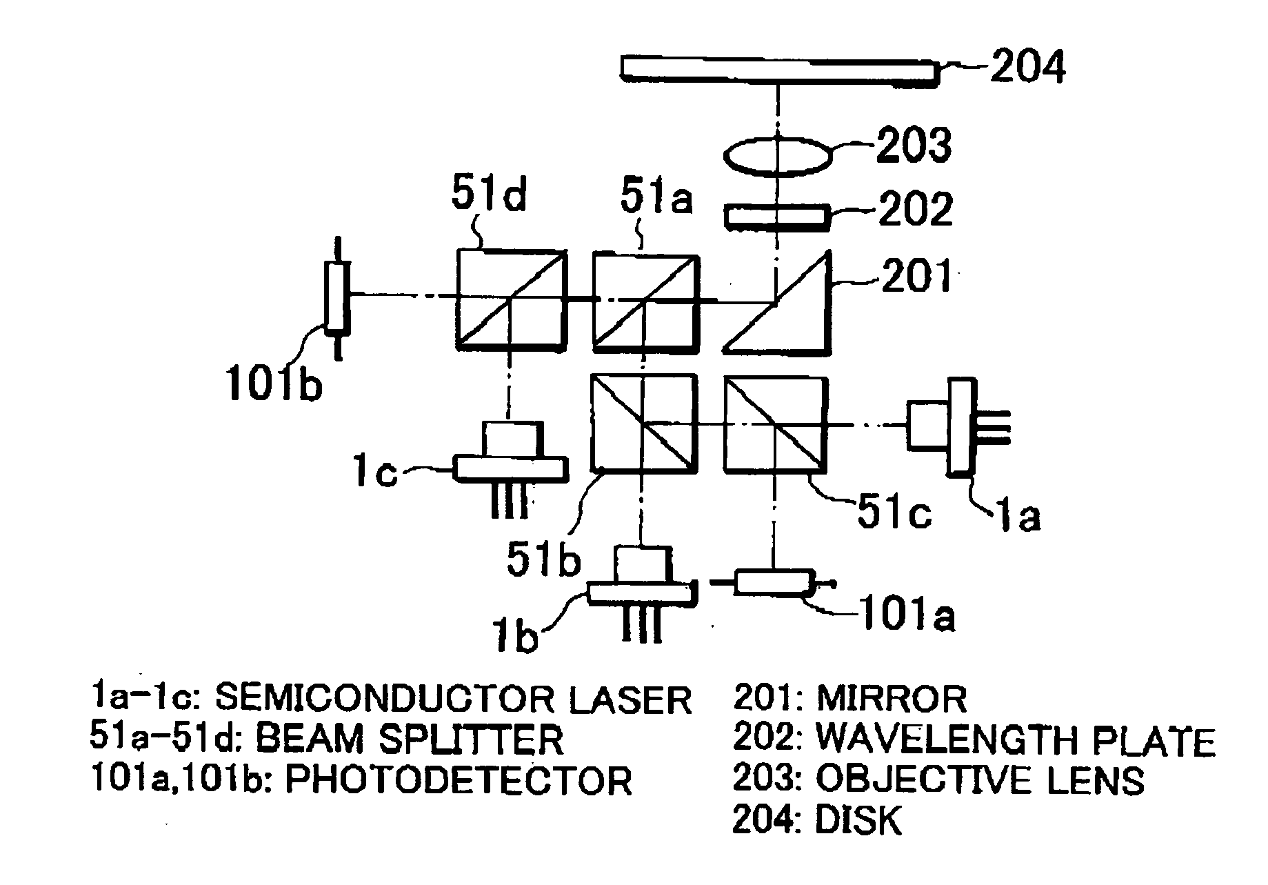
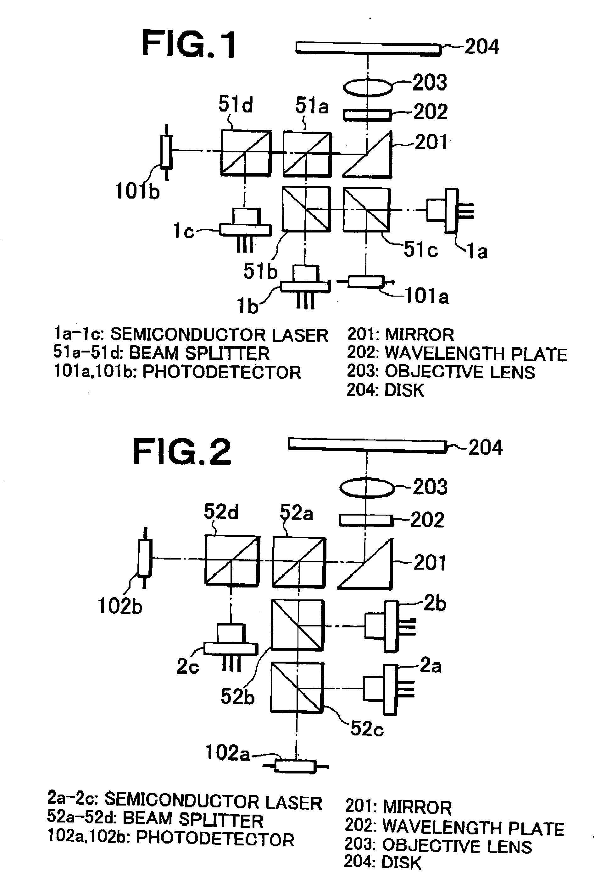
[0156]FIG. 1 shows the first embodiment of the optical head apparatus according to the present invention. Wavelengths of the semiconductor lasers 1a, 1b, and 1c are 780 nm, 660 nm, and 400 nm, respectively. The beam splitter D is used as a beam splitter 51a. Any of the beam splitters K, O, and X is used as a beam splitter 51b. Any of the beam splitters L, Q, W, S, V, and Y is used as the beam splitter 51c. Any of the beam splitters G, J, M, N, T, U, W, X, and Y is used as the beam splitter 51d.
[0157] Light having a wavelength of 400 nm and emitted from the semiconductorlaser 1c enters, as S-polarized, into the beam splitter 51d. Almost all of the light is reflected therefrom and passes through the beam splitter 51a. This light is then reflected by a mirror 201 and transformed into circula...
ninth embodiments (
4. Fifth to Ninth Embodiments (Type 2)
[0209] The fifth to ninth embodiments of the present invention each have three light sources and one photodetector.
(Fifth Embodiment)
[0210]FIG. 5 shows the fifth embodiment of the optical head apparatus according to the present invention. The wavelengths of the semiconductor lasers 5a, 5b, and 5c are 400 nm, 660 nm, and 780 nm, respectively. The beam splitter G is used as a beam splitter 55a. Any of the beam splitters H and U is used as a beam splitter 55b. Any of the beam splitters I, S, T, and Y is used as the beam splitter 55c.
[0211] Light having a wavelength of 400 nm and emitted from the semiconductor laser 5a enters, as S-polarized, into the beam splitter 55a. Almost all of the light is reflected therefrom and further reflected by the mirror 201. This light is transformed into circularly polarized light from linearly polarized light by a wavelength plate 202, and is converged on a disk 204 according to the next-generation standard by a...
tenth embodiment (
5. Tenth Embodiment (Type 3)
[0283] The tenth embodiment of the optical head apparatus according to the present invention has two light sources and two photodetectors. However, one of the two light sources is constructed by integrating two light sources.
[0284]FIG. 10 shows the tenth embodiment of the optical head apparatus according to the present invention. The semiconductor laser 10b is a semiconductor laser which integrates two semiconductor lasers. The structure of the laser will be described later with reference to FIG. 72. The wavelength of the semiconductor laser 10a is 400 nm, and the semiconductor laser 10b has wavelengths of 660 nm and 780 nm. The beam splitter A is used as a beam splitter 60a. Any of the beam splitters G, J, M, N, T, U, W, X, and Y is used as a beam splitter 60b. Any of the beam splitters S, V, and Y is used as a beam splitter 60c.
[0285] Light having a wavelength of 400 nm and emitted from the semiconductor laser 10a enters, as P-polarized, into the beam...
PUM
Abstract
Light emitted from a light source and having a wavelength of 400 nm is reflected by a beam splitter (BS), and converged on a disk according to a next-generation standard. Reflection light therefrom passes through the BS and is received by a photodetector. Light emitted from a light source and having a wavelength of 660 nm is reflected by the BS and passes through the BS, and converged on a disk according to a DVD standard. Reflection light therefrom passes through the BS and is received by the photodetector. About 50% of light emitted from a light source and having a wavelength of 780 nm is reflected by the BS. The light passes through the BS and is then converged on a disk according to a CD standard. Reflection light therefrom passes through the BS. About 50% of the light passes through the BS and is received by the photodetector. Thus, recording and reproduction can be performed on any of disks according to a next-generation standard, DVD standard, and CD standard. With respect to disks according to the next-generation standard, a high optical output is obtained during recording and a high S / N ratio is obtained during reproduction. With respect to disks according to the CD standard, the amount of light received by the photodetector does not substantially vary even when birefringence of a disk varies.
Description
BACKGROUND OF THE INVENTION [0001] 1. Field of the Invention [0002] The present invention relates to an optical head apparatus and an optical information recording or reproducing apparatus for recording or reproducing information with respect to several types of optical recording mediums having different standards. [0003] 2. Description of Related Art [0004] A recording density in an optical information recording or reproducing apparatus is inversely proportional to a square of a diameter of a condensed spot formed on an optical recording medium by an optical head apparatus. That is, the smaller the diameter of the condensed spot is, the higher the recording density becomes. The diameter of the light convergence spot is proportional to a wavelength of a light source in the optical head apparatus, and is inversely proportional to a numerical aperture of the objective lens. That is, when the wavelength of the light source is shorter, and the numerical aperture of the objective lens is...
Claims
Application Information
Patent Timeline
Application Date:The date an application was filed.
Publication Date:The date a patent or application was officially published.
First Publication Date:The earliest publication date of a patent with the same application number.
Issue Date:Publication date of the patent grant document.
PCT Entry Date:The Entry date of PCT National Phase.
Estimated Expiry Date:The statutory expiry date of a patent right according to the Patent Law, and it is the longest term of protection that the patent right can achieve without the termination of the patent right due to other reasons(Term extension factor has been taken into account ).
Invalid Date:Actual expiry date is based on effective date or publication date of legal transaction data of invalid patent.

