[0011] The present invention has been made to solve the above-described problems, and an object thereof is to provide an optical disk apparatus having a function of speedily calculating the amount of optical axis misalignment of an optical
pickup to allow a wobble signal to be obtained early when initially
spinning up an optical disk.
[0014] In accordance with the arrangement above, since the amount of optical axis misalignment of the optical pickup is calculated by a calculation formula, it is possible to find the amount of optical axis misalignment speedily and thereby to obtain a wobble signal early when initially spinning up the optical disk, whereby the type of the loaded optical disk can be determined speedily, which therefore makes it possible to shorten the time before
reproduction, resulting in an improvement in user-friendliness.
[0017] In accordance with the arrangement above, since the amount of optical axis misalignment of the optical pickup is calculated by a calculation formula, it is possible to find the amount of optical axis misalignment speedily and thereby to obtain a wobble signal early when initially spinning up the optical disk, whereby the type of the loaded optical disk can be determined speedily, which therefore makes it possible to shorten the time before
reproduction, resulting in an improvement in user-friendliness.
[0019] Accordingly, if there is provided a
light detector having four light detecting elements that correspond, respectively, to four divided light receiving regions, it is possible to calculate the amount of optical axis misalignment X speedily by a calculation formula X=[(A+B)−(C+D)] / (A+B+C+D) [%], and therefore to detect a wobble signal by (A+B)−(C+D) after an offset value according to the amount of optical axis misalignment X is added to a tracking drive voltage. Thus obtained wobble signal shows a high accuracy with an extremely small amount of optical axis misalignment of the optical pickup in the tracking direction and thereby a high S / N ratio.
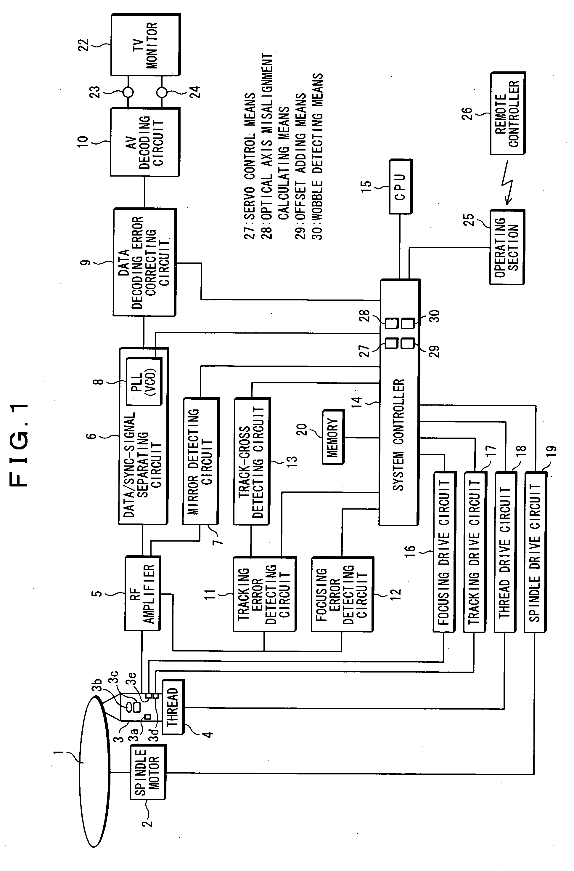
[0020] As mentioned above, in accordance with the present invention, in an optical disk apparatus including an optical pickup to reproduce or
record / reproduce information onto / from an optical disk, the optical pickup being adapted to collect emitted light from a luminous element for emitting a
laser beam on the optical disk through an objective lens to form a small
light spot and adapted to make reflected light from the optical disk incident into a
light detector divided into four regions through the objective lens to obtain a readout signal, there is provided a
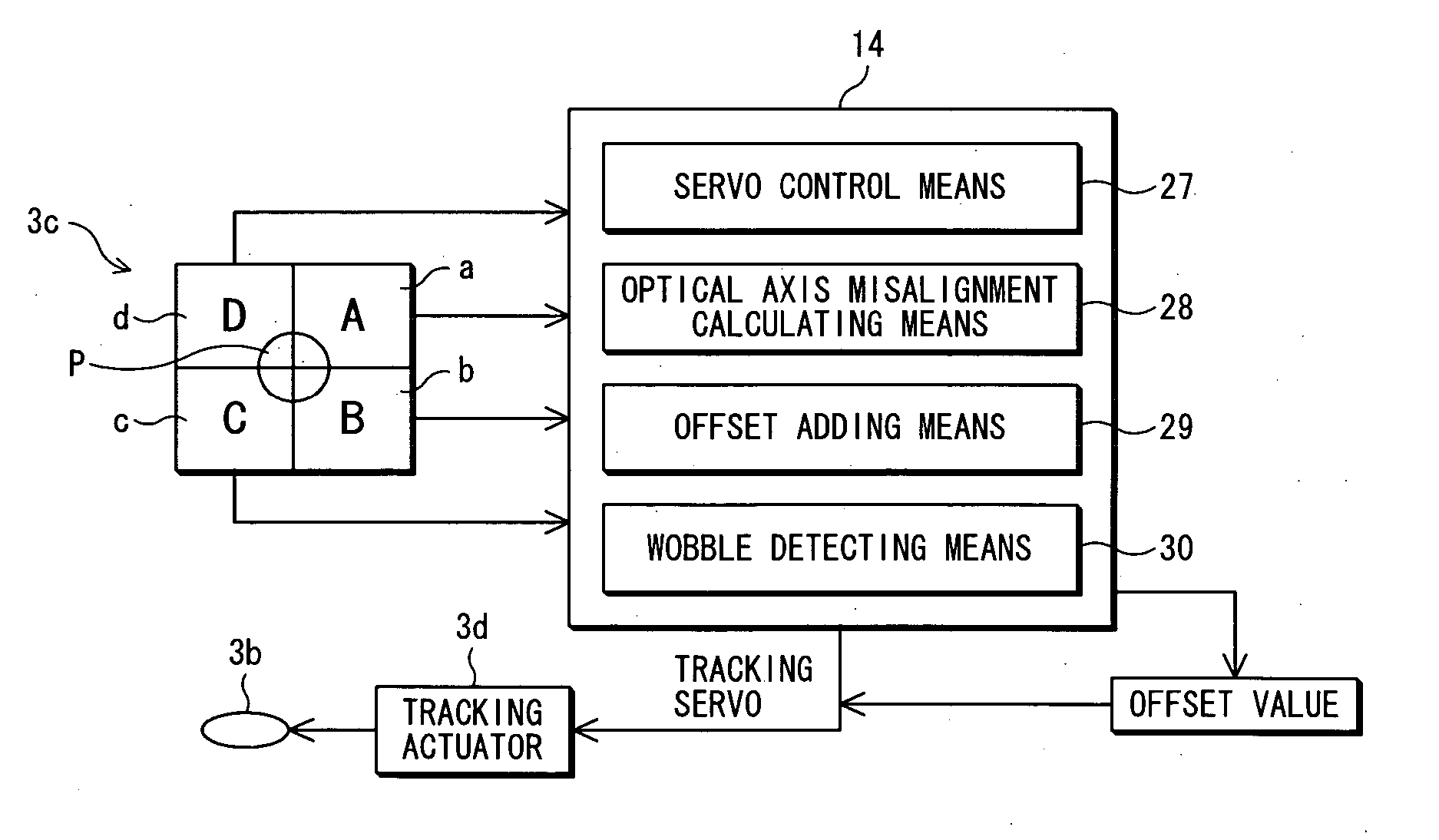
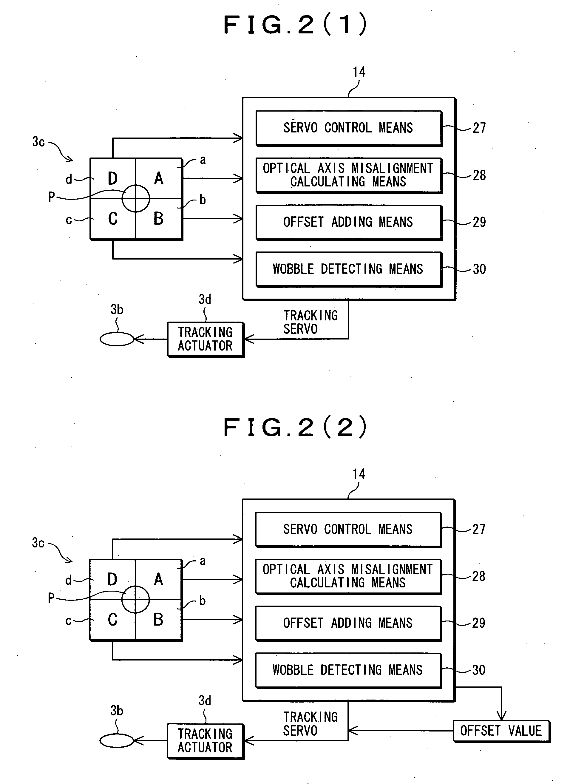
system controller having:
servo control means for turning the focusing servo for the objective lens in the optical pickup on while turning the tracking servo therefor off when initially spinning up the optical disk; optical axis misalignment calculating means for calculating the amount of optical axis misalignment X of the objective lens in the optical pickup in the tracking direction by a calculation formula X=[(A+B)−(C+D)] / (A+B+C+D) [%] with the focusing servo on while the tracking servo off, where A, B, C, and D represent the amount of light received at light detecting elements corresponding to the respective four divided regions in the
light detector; offset adding means for adding an offset value according to the amount of optical axis misalignment X to a tracking drive voltage after turning the tracking servo on; and wobble detecting means for detecting a wobble signal by (A+B)−(C+D) after the offset value is added, whereby since the amount of optical axis misalignment of the optical pickup can be calculated by a calculation formula, it is possible to find the amount of optical axis misalignment speedily and thereby to obtain a wobble signal early when initially spinning up the optical disk, whereby the type of the loaded optical disk can be determined speedily, which therefore makes it possible to shorten the time before reproduction, resulting in an improvement in user-friendliness.
[0021] Also, in accordance with the present invention, in an optical disk apparatus including an optical pickup to reproduce or
record / reproduce information onto / from an optical disk, the optical pickup being adapted to collect emitted light from a luminous element for emitting a
laser beam on the optical disk through an objective lens to form a small
light spot and adapted to make reflected light from the optical disk incident into a light
detector through the objective lens to obtain a readout signal, there is provided a
system controller having: servo control means for turning the focusing servo for the objective lens in the optical pickup on while turning the tracking servo therefor off when initially spinning up the optical disk; optical axis misalignment calculating means for calculating the amount of optical axis misalignment of the objective lens in the optical pickup in the tracking direction by a calculation formula with the focusing servo on while the tracking servo off; offset adding means for adding an offset value according to the amount of optical axis misalignment to a tracking drive voltage after turning the tracking servo on; and wobble detecting means for detecting a wobble signal after the offset value is added to the tracking drive voltage, whereby since the amount of optical axis misalignment of the optical pickup can be calculated by a calculation formula, it is possible to find the amount of optical axis misalignment speedily and thereby to obtain a wobble signal early when initially spinning up the optical disk, whereby the type of the loaded optical disk can be determined speedily, which therefore makes it possible to shorten the time before reproduction, resulting in an improvement in user-friendliness.

