Electric rotary shaver

a rotary shaver and electric technology, applied in the direction of metal working devices, etc., can solve the problems of limited range, inability to move, and inability to remove the locking member, and achieve the effect of greatly facilitating the attachment and detachment of the locking member

Active Publication Date: 2007-05-29
IZUMI PROD CO
View PDF19 Cites 25 Cited by
  • Summary
  • Abstract
  • Description
  • Claims
  • Application Information

AI Technical Summary

Benefits of technology

[0019]It is an object of the present invention to provide an electric rotary shaver in which the movable range of the outer cutters can be increased, the spacing of the outer cutters can be narrowed so that the size of the cutter head can be reduced, the operation performed by the fingertips when shaving debris is cleaned away can be simplified, and the retaining plate or inner cutter holder can be stably held without complicating the structure.
[0040]Furthermore, a projection used to catch the fingers can be provided so as to surround the center of the cutter frame on the locking member. With this projection, attachment and detachment of the locking member are greatly facilitated. This projection used to catch the fingers can be split in the circumferential direction, and it also can be formed as a circumferentially continuous ring.

Problems solved by technology

In the shaver described in Japanese Patent No. 2853812, the movable range (range of vertical movement and tilting range) of the shaving units comprising outer cutters and inner cutters is limited to the movable range of the elastic arms that are integrated with the retaining plate and is therefore unavoidably extremely small.
Accordingly, the outer cutters cannot sufficiently conform to indentations and projections or variations in the inclination of the shaving surface (skin), and the shaving characteristics are therefore poor.
Furthermore, when shaving debris is cleaned away, the arms that protrude outward from the center (toward the inside wall of the cutter frame) are pressed toward the center with the fingertips, so that the tip ends of the arms are disengaged from the inside wall of the cutter frame; accordingly, a fine operation using the fingertips is required, and the operating characteristics are poor.
However, in order to remove the retaining plate for the purpose of cleaning away shaving debris, it is necessary to turn the locking body (50) with the fingertips, thus making the operating characteristics poor.
As a result, the size of the cutter frame tends to increase.
Likewise, in cases where two outer cutters are used, it is necessary to broaden the spacing of the outer cutters, and this has been a serious problem.
The operating characteristics are thus poor.
Accordingly, the locking bolt 6 tends to be unstable, and the inner cutter holder 3 that is held here is also unstable.
In such cases, however, since there is only a single coil spring, it is necessary to use a coil spring with a strong spring force.
Consequently, the detachment operating characteristics of the locking body (50) or locking bolt (6) when shaving debris is cleaned away are poor.
Furthermore, the structure used to position the retaining body (20) or inner cutter holder (3) in the radial direction becomes complicated.

Method used


Image

  • Electric rotary shaver
  • Electric rotary shaver
  • Electric rotary shaver

Examples


Embodiment Construction

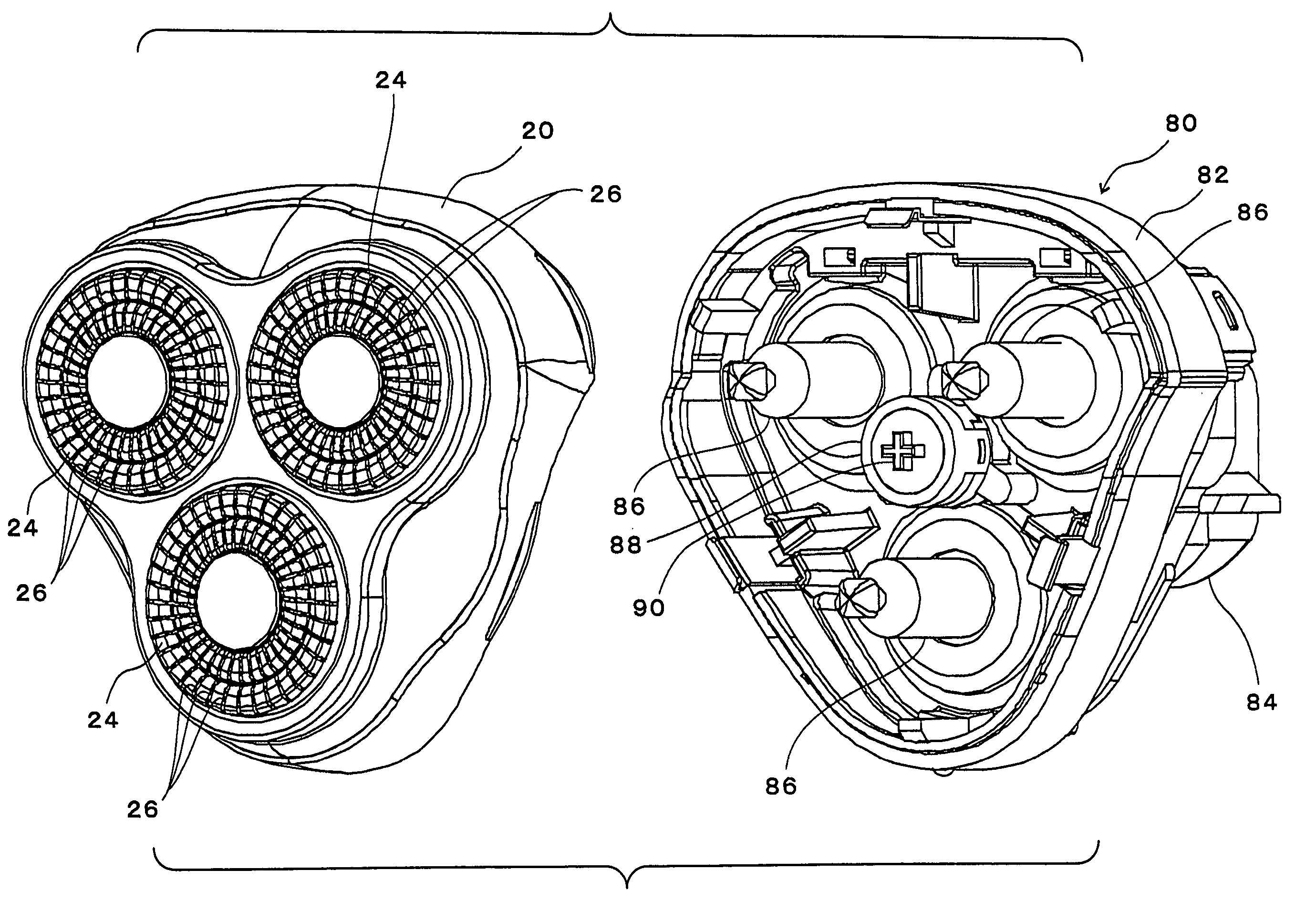
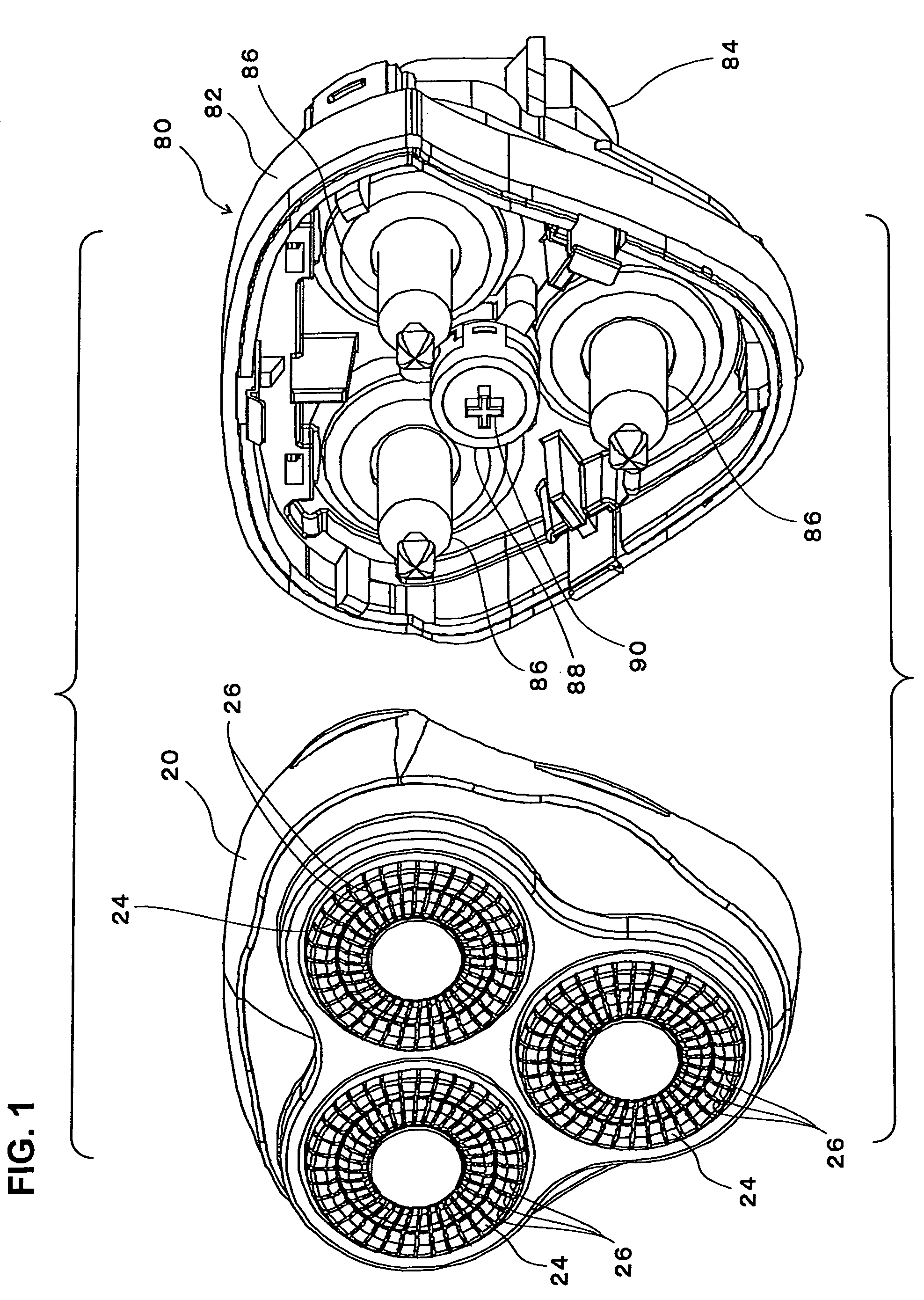
[0050]In FIGS. 1 through 7, the reference numeral 20 indicates a cutter frame; three outer cutter mounting holes 22 (see FIGS. 4 and 7) are formed in the substantially triangular bottom surface (or top surface) of this cutter frame 20.

[0051]The reference numerals 24 indicate outer cutters. These outer cutters have a substantially circular disk form cap shape, and numerous slits 26 are formed in a radial configuration in the circular portions of these outer cutters, which are made of thin metal plates (see FIGS. 1 and 4). Annular outer circumferential rims 28 made of a synthetic resin are integrally fastened to the opening rims of the outer cutters 24, and three projections 30 are formed to protrude from the edges of these outer circumferential rims 28 at equal intervals in the circumferential direction so that they are in positions that are located slightly to the inside of the outer circumferential surfaces (see FIG. 4).

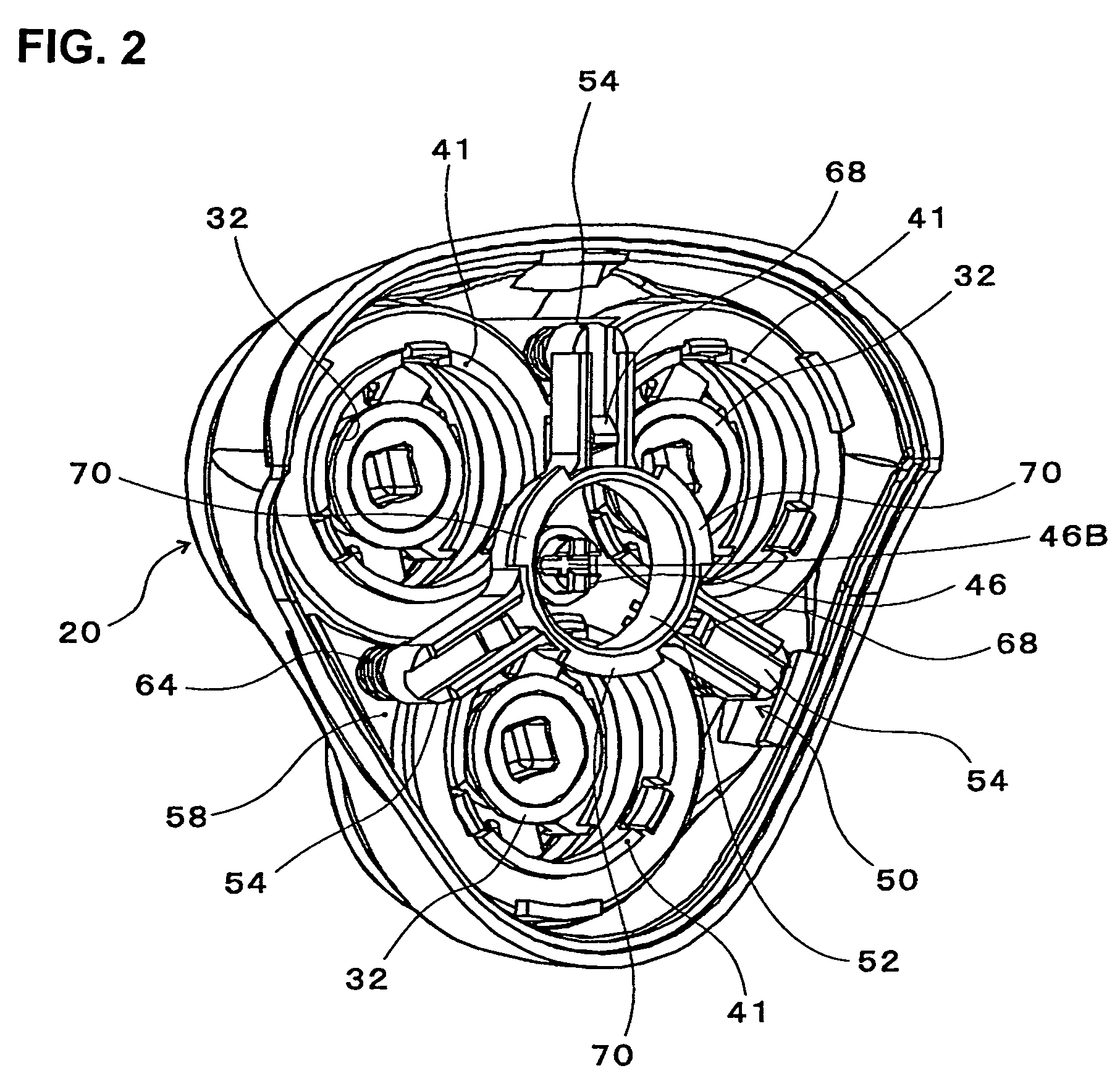
[0052]The reference numerals 32 indicate inner cutters. Each i...


PUM


Abstract

An electric rotary shaver including: a locking member (50) having a plurality of arms (54) outwardly extending from the center, a cutter retaining plate (38) that engages with outer circumferential rims of outer cutters (24) and rotatably holds inner cutters (32), guide pins (56) provided on the tip ends of the arms (54) and slidably pass through the cutter retaining plate (38), permanent magnets (62) fastened to the cutter frame (20) and attach the guide pins (56) by magnetic attraction in a detachable manner, compression coil springs (64) mounted on the guide pins (56) and provided in a compressed state between the arms (54) and the cutter retaining plate (38), and anchoring elements (66, 68) which prevents a locking member (50) from being separated from the cutter retaining plate (38) by more than a predetermined gap.

Description

BACKGROUND OF THE INVENTION[0001]1. Field of the Invention[0002]The present invention relates to an electric rotary shaver which causes inner cutters to rotate while contacting substantially disk-form outer cutters, and uses the inner cutters to cut whiskers that are introduced into slits formed in the outer cutters.[0003]2. Description of the Related Art[0004]In electric shavers of this type, shavers that have a plurality of outer cutters are universally known. For example, such shavers include shavers in which two outer cutters are installed side by side in close proximity to each other, and shavers in which three outer cutters are disposed at the vertices of an equilateral triangle. In this structure, in order to improve the shaving characteristics, it is necessary to arrange the outer cutters so that these cutters are depressable and tiltable, thus causing the outer cutters to incline in conformity to the curvature of the shaving surface.[0005]In the shaver disclosed in Japanese...

Claims


Application Information

Patent Timeline
Patent Type & Authority Patents(United States)
IPC IPC(8): B26B19/04B26B19/14
CPCB26B19/14B26B19/145
Inventor KOIKE, HIDEAKI
Owner IZUMI PROD CO
Why Eureka
Try Eureka